MTD 112-060A User Manual
Page 5
Attention! The text in this document has been recognized automatically. To view the original document, you can use the "Original mode".
Upper
Handle
Hex Bolt (F)
-5.
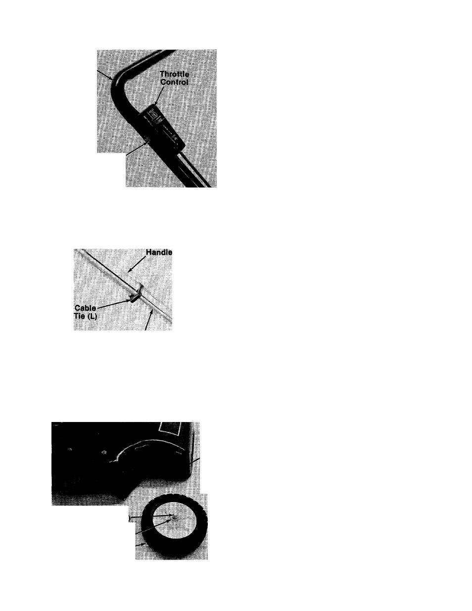
Place the throttle control in position on
right
side of upper handle. Secure with hex bolt (F)
and lock nut (G). See figure 4.
FIGURE 4.
Throttle
Control
Cable
N.
FIGURE 5.
Four
Cutting
Heights
Shoulder Bolt (M
Belleville Washer (J)
Wheel-
FIGURE 6.
-6. Secure throttle control cable to upper and
lower handles with cable ties (L) provided. See
figure 5.
The four holes provide four cutting heights for
your mower. Use the same hole location for all
four wheels when assembling.
7. To assemble the front wheels (see figure 6):
A. Place shoulder bolt (M) through wheel.
B. Place one belleville washer (J) on shoulder
bolt, with the crown side of washer against
the wheel (away from deck).
C.
Secure wheel to deck with one belleville
washer (J) on the inside of the deck
(cupped side against the deck) and hex nut
(K).
8. To assemble the rear wheels:
A. Place shoulder bolt (H) through rear wheel.
B. Place spacer (I) on shoulder bolt, next to
wheel.
C. Place one belleville washer (J) on shoulder
bolt, with the crown side of washer against
the spacer (away from deck).
D. Secure wheel to deck with one belleville
washer (J) on the inside of the deck
(cupped side against the deck) and hex nut
(K).