Operation – MTD 248-650A User Manual
Page 5
Attention! The text in this document has been recognized automatically. To view the original document, you can use the "Original mode".
FIGURES.
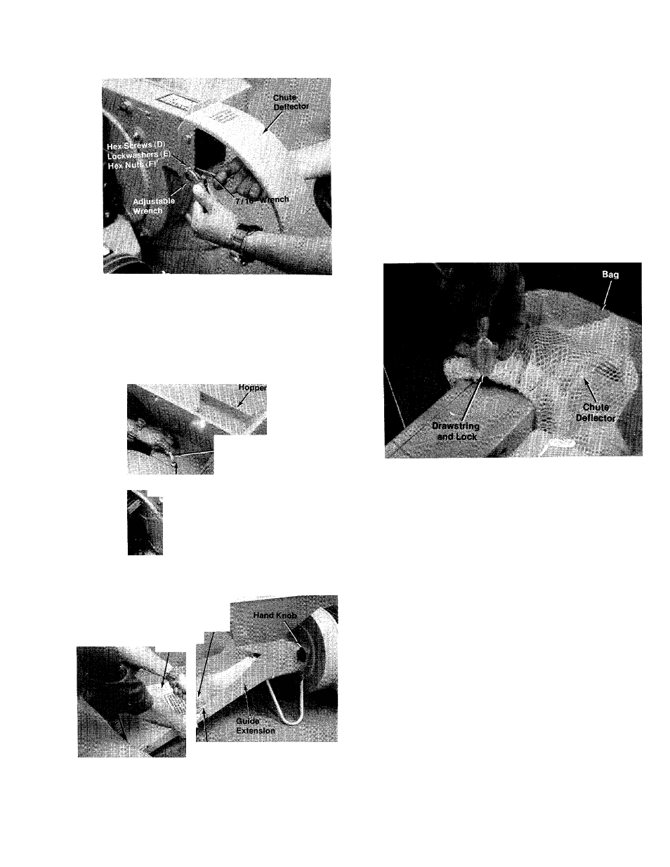
3. Hopper:
A. Place the hopper on the shredder, start all
three self threading screws (A) by hand
and then tighten with a I/
2
” wrench. See
figure 4.
1/2”.Wronoh
Hex Screw (A)
/■v
FIGURE 4.
Adjustabl»
Wrench
Upper Guide
Extensión
7/16" Wrench
4. Upper Guide Extension:
A. Loosen hand knob on right hand side of
shredder. See figure 5.
B. Place upper guide extension in place on
guide extension and secure with four hex
screws (B) and hex center locknuts (C). A
7/16” wrench and adjustable wrench is
required. See figure 5.
5. Place the bag over the chute deflector and pull
draw string and lock. See figure 6.
FIGURES.
OPERATION
1. Service engine with gas and oil. See engine
manual packed with shredder for complete
instructions for the care and maintenance of
engine. READ DIRECTIONS CAREFULLY.
2. When ready to start engine, place throttle
control lever in CHOKE position and start
engine in accordance with instructions in
engine manual. After engine starts, move
throttle control lever to RUN position. The
engine is stopped by placing control lever in
the STOP position.
A<
FIGURES.
^CAUTION
The manufacturer recommends that
the operator wear safety glasses or
some other suitable eye protection
as it is possible for chips to be
ejected out of the inlet openings
while feeding material.