Pre-assembly, Assembly, Instructions – MTD 248-650A User Manual
Page 4: Rm nni etii mi, Assembly instructions, Rrji, Rrrt, Rrri
Attention! The text in this document has been recognized automatically. To view the original document, you can use the "Original mode".
PRE-ASSEMBLY
NOTE
The right and left side of your shred
der is determined from operator’s
position.
Before any step is undertaken, the instructions for
that step should be read through.
TOOLS REQUIRED:
1. (1) 7/16” Open End or Box Wrench
2. (1)
1
/
2
” Open End or Box Wrench
3. (1) Adjustable Wrench.
MATERIALS REQUIRED:
1. Funnel (for gas and oil—NOTE: Do not mix).
2. S.A.E. 30 011—23/4 pints.
3. Gas (regular).
4. Cleaning rag.
PARTS IN CARTON
B
§
m
rrji
rrri
rrrt
q™
rm nni ETii mi
FIGURE 2.
ASSEMBLY
INSTRUCTIONS
FIGURE 1.
NOTE
The letters listed below will be re
ferred to throughout the following
text for easier hardware identifica
tion.
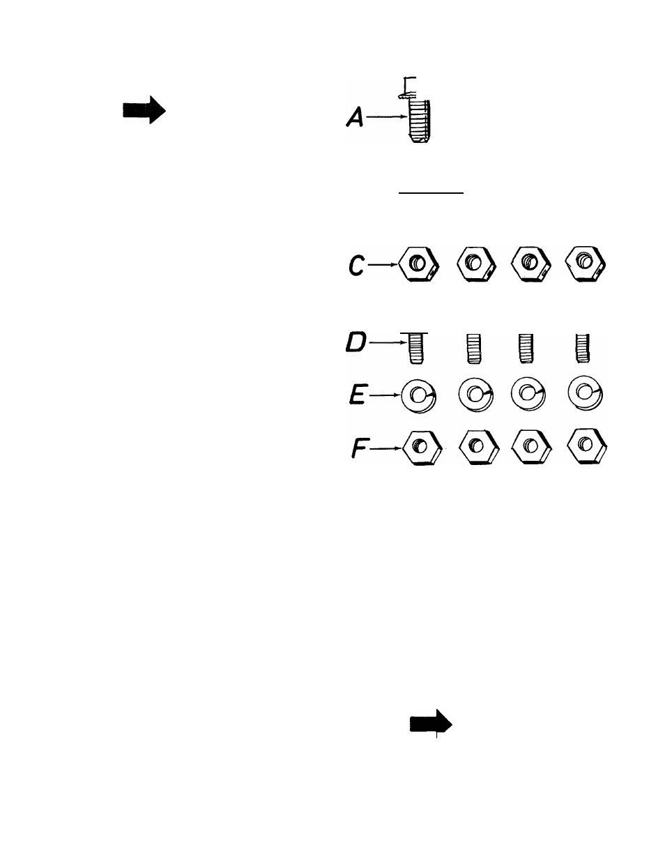
LIST OF CONTENTS IN HARDWARE PACK:
A (3) Hex washer head self threading screws
B (4) Hex screws V
4-20
X
V
2
” long
C (4) Hex center locknuts ■'A-20 thread
D (4) Hex screws V4-2O x V
2
” long
E (4) Lockwashers ■'A” screw
F (4) Hex center locknuts V
a
-20 thread
1.
Remove the shredder, parts pack and all
literature from the carton before discarding
carton.
2. Chute Deflector:
A. Place the chute deflector, in position on
the left hand side of shredder.
B. Secure with four hex screws (D), lock-
washers (E) and hex center locknuts (F).
See figure 3.
NOTE
Heads of screws are assembled
from the inside, nuts and washers
go on the outside. Start all four
screws, nuts and washers by hand,
then
tighten
with
an
adjustable
wrench and 7/16” wrench.