Troy-Bilt TUFFY 634A User Manual
Page 8
Attention! The text in this document has been recognized automatically. To view the original document, you can use the "Original mode".
4.
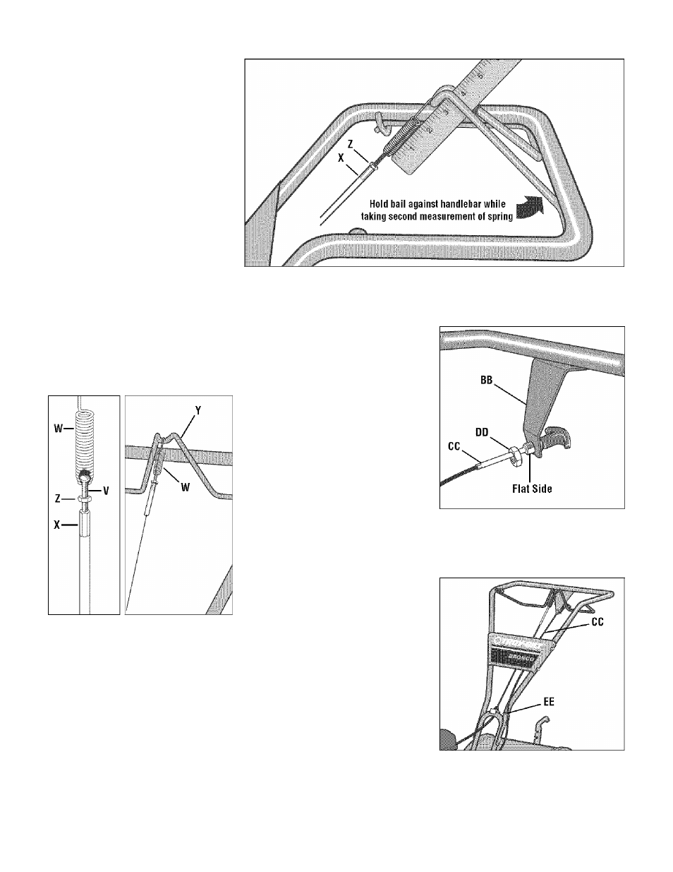
Check for correct tension on the forward
drive belt by taking two measurements of
the cable spring, as follows:
a. With the Forward Clutch Bail (Y. Fig. 2
6) in an open (released) position, measure
the length of the cable spring (W) from the
outermost coil to the outermost coil.
b. Squeeze the Forward Clutch Bail against
the handlebar (see Fig. 2-7) and re-mea
sure the spring length. The belt tension is
correct if this second measurement is be
tween 1/16" to 3/16" longer than the first
measurement. If so. turn the hex nut (Z,
Fig. 2-7) tightly against the cable adjuster
(X) while preventing the cable adjuster
from turning.
c. If the spring length is incorrect, you
must adjust the cable tension as described
in
Checking and Adjusting Forward Drive
Belt Tension in Section 5. Incorrect cable
tension can result in belt slippage (cable
tension too loose), or unintentional tine
movement when the clutch bail is in Neu
tral (cable tension too tight).
Fig. 2-5: Cable
spring and
adjuster.
Fig. 2-6: Attach forward
clutch cable spring to
forward clutch bail.
Fig. 2-7: To check forward belt tension, take two measurements of the length of the coils in the
spring
—
first with the bail open, then with the bail held against the handlebar.
STEP 5: INSTALL REVERSE CLUTCH
CABLE (MODEL 634AONLY)
1. Unwrap the reverse clutch cable (CC,
Fig. 2-8 and Fig. 2-9) from its shipping po
sition and route it up to the handlebar. Be
sure that the cable is routed beneath the
Forward Clutch Bail.
2.
Insert the cable (CC, Fig. 2-8)throughthe
slot in the cable bracket and position the flat
side of the threaded assembly next to the
flat side of the hole. Slide the hex nut (DD)
up the cable and tighten it securely.
3.
Fasten the reverse clutch cable to the
left side handlebar with a cable tie (EE, Fig.
2-9).
4.
Testthe function of the reverse clutch by
pulling out and releasing the cable knob.
The knob should return to its neutral posi
tion (resting against bracket). If it doesn’t,
contact your local dealer or Troy-Bilt LLC
for technical assistance.
Fig. 2-8: Install reverse cable bracket and
reverse clutch cable.
Fig. 2-9: Route reverse clutch cable (CC) as
shown. Attach with cable tie (EE).