Bold tines, Warning – Troy-Bilt TUFFY 634A User Manual
Page 18
Attention! The text in this document has been recognized automatically. To view the original document, you can use the "Original mode".
A
WARNING:
Before inspecting, cleaning or servicing the machine, shut off engine, wait for ail
moving parts to come to a complete stop, disconnect spark plug wire and move wire away from
spark plug. Failure to follow these instructions can result in serious personal injury or property
damage.
4.
The gear oil level is correct if the gear oil
is approximately halfway up the side of the
main drive shaft.
5.
If the gear oil level ¡slow, add gear oil as
described next. If the gear oil level is okay,
securely replace the oil fill plug.
IMPORTANT;
Do not operate the tiller if the
gear oil level is low. Doing so will result in
severe
damage
to
the
transmission
com
ponents.
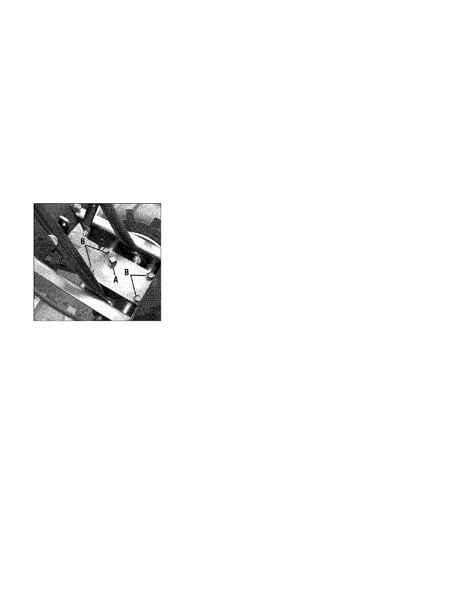
Figure 5-2: Remove oil fill plug (A) to check
gear oil level and to add gear oil. Remove
four cover screws (B) to drain gear oil.
6
.
If adding only a few ounces of gear oil,
use API rated GL-4 or GL-5 gear oil having
a viscosity of SAE 140. SAE 85W-140 or
SAE 80W-90. If refilling an empty trans
mission, use only GL-4 gear oil having a
viscosity of SAE 85W-140 or SAE 140.
IMPORTANT;
Do not use automatic trans
mission fluid or motor oil in the transmis
sion.
7. While checking frequently to avoid over
filling, slowly add gear oil into the oil fill
hole until it reaches the halfway point on
the drive shaft.
8
.
Securely replace the oil fill plug.
B. To Drain the Transmission Gear Oil;
The transmission gear oil does not need to
be changed unless it has been contaminat
ed with dirt, sand or metal particles.
1.
Drain gasoline from the fuel tank or run
the engine until the fuel tank is empty. See
“DANGER” statement below.
A
WARNING:
Gasoline is
highly flammable and its vapors
are explosive. Follow these
safety practices to prevent
personal injury or property
damage from fire or explosion.
• Allow the engine and muffier to cool
for at least two minutes before drain
ing the tiller’s gasoline tank.
• Do not allow open flames, sparks,
matches or smoking in the area.
• Wipe away spills and push tiller away
from spilled fuel.
• Use only an approved fuel container
and store it safely out of the reach of
children.
• Do not store gasoline in an area where
its vapors could reach an open flame
or spark, or where ignition sources are
present (such as hot water and space
heaters,
furnaces,
clothes
dryers,
stoves, electric motors, etc.)
2.
Drain the oil from the engine.
3.
Remove four screws (B, Figure 5-2) and
remove transmission cover and gasket.
4.
Remove the ieft-side wheei.
5.
Tilt the left-side wheel shaft into a drain
pan and ailow the gear oil to drain through
the top of the transmission.
6
.
Reinstall the wheel.
7.
Install a new gasket (do not reuse old
gasket) and reinstall the transmission cov
er.
8
.
Refill the transmission using GL-4 gear
oil (SAE 85W-140 or SAE 140).
9.
Refill the engine with motor oil and re
plenish the fuel tank with gasoline.
BOLD TINES
The bolo tines will wear with use and
should be inspected at the beginning of
each tilling season and after every 30 oper
ating hours. The tines can be replaced ei
ther individually or as a complete set. See
the Parts List pages for tine identification
and part numbers.
A. Tine Inspection:
With use, the tines will become shorter,
narrower and pointed. Badly worn tines
will result in a loss of tilling depth, and re
duced effectiveness when chopping up
and turning under organic matter.
B. Removlngdnstalling a Single Tine:
1. With the engine shut off and the spark
plug wire disconnected, remove the two
screws (A, Figure 5-3), lock washers (E)
and nuts (B) that attach a single tine to a
tine holder. If needed, use penetrating oil
on the nuts.
2.
When installing a single tine, be sure to
position it so that its
cutting edge (sharp)
will enter the soil first as the tiller moves
forward.
C. Removinginstalling a Tine Assembly;
1.
A tine assembly consists of eight tines
mounted on a tine holder.
2.
If removing both tine assemblies, mark
them “left” and “right” before removal. Re
move the screw (C, Figure 5-3), lock wash
er (E) and locknut (D) that secure the tine
assembly to the tine shaft. If necessary,
use a rubber mallet to tap the tine assem
bly outward off the shaft.
3.
Before reinstalling the tine assembly, in
spect the tine shaft for rust, rough spots or
burrs. Lightly file or sand, as needed. Ap
ply a thin coat of grease to the shaft.
4.
Install each tine assembly so that
the
cutting (sharp) edge of the tines will enter
the soil first when the tiller moves forward.
Secure the tine assembly to the tine shaft
using the screw and locknut
18