Assembly instructions, Attaching the upper guide assembly, Hex bolt – MTD 645C thru 650C User Manual
Page 3: To remove shredder from carton, Tools required for assembly, Attaching the hopper assembly, Assembly instructions ct
Attention! The text in this document has been recognized automatically. To view the original document, you can use the "Original mode".
ASSEMBLY INSTRUCTIONS
Ct
ATTACHING THE UPPER
GUIDE ASSEMBLY
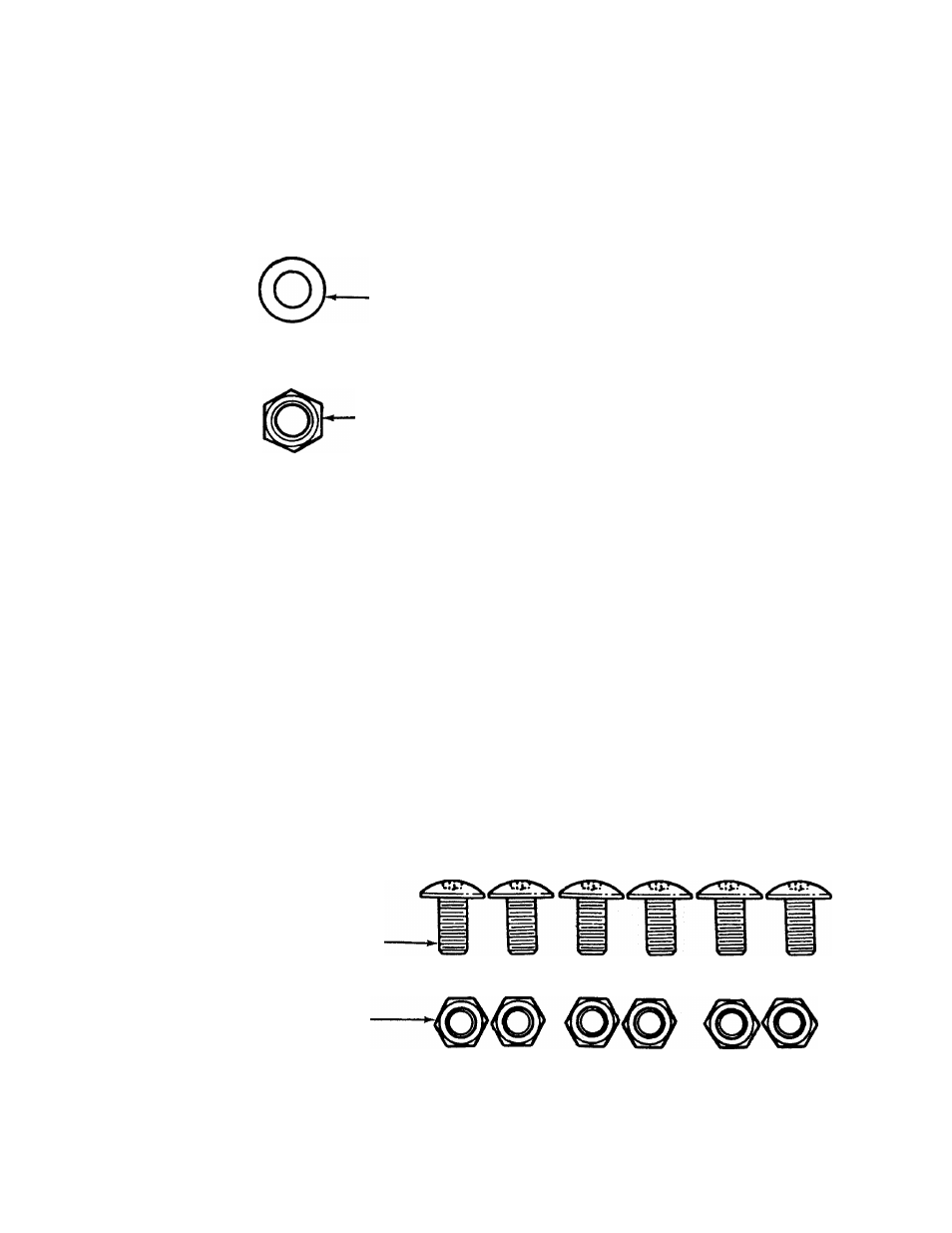
Flat
Washer
5/16" I.D.
Hex Lock
Nut 5/16-18
Thread
Hex Bolt
-5/16-18
X
8-3/8" Long
= =x
B
IMPORTANT: This unit is shipped WITHOUT
GASOLINE or OIL. After assemijiy, see separate
engine manual for proper fuel and engine oil rec
ommendations.
NOTE:
To determine right and left hand sides of your
shredder, stand behind and face the hopper (engine
is at the front of the unit).
Your shredder has been completely assembled at the
factory, except for the hopper assembly (hopper hood
and upper guide extension have been sub-assem
bled), upper guide assembly, chute deflector and the
catcher bag. The hardware pack and a pair of safety
glasses are also included in the carton.
The hardware pack contains the parts shown in figure
1 (shown full size).
TO REMOVE SHREDDER FROM CARTON
Cut the corners of the carton. Remove all packing
inserts. Roll shredder out of carton. Make certain all
parts and literature have been removed before the
carton is discarded.
TOOLS REQUIRED FOR ASSEMBLY
(1) Phillips Screwdriver
(2) 1/2" Wrenches (one must be a socket wrench)
(2) 7/16" Wrenches or Adjustable Wrenches
ATTACHING THE HOPPER ASSEMBLY
Truss Machine
Screws 1/4-20 x 1/211
Long
Hex Lock Nuts
1/4-20 Thread
FIGURE 1.