21 assembly, A warning, A danger – Troy-Bilt 47330 User Manual
Page 6
Attention! The text in this document has been recognized automatically. To view the original document, you can use the "Original mode".
Section
21 Assembly
A
WARNING
To prevent personal injury or property
damage, do not start the engine until all
assembly steps are complete and you
have read and understand the safety and
operating instructions in this Manual.
INTRODUCTION
For best results, read these instructions in
their entirety before you attempt to assem
ble your new equipment.
STEP 1: UNPACKING INSTRUCTIONS
1. inspect the unit immediately. If you find
or suspect damage, contact the carrier
(trucking company) right away and tell the
carrier you wish to file a claim.
2. Remove any packing materiai from
around the unit. Remove the chipper
chute (item 2, Figure 2-1) and clutch lever
(item 7, Figure 2-1) from the top of the
machine. Remove the package containing
loose parts. Be sure to check thoroughly
for any parts before disposing of the
carton or any of the packing materials.
3. Use a pry bar to remove any wooden
blocks from the front stand assembly.
Have an assistant help you move the unit
off the wood pallet.
STEP 2: CHECK CARTON CONTENTS
Check that you have the items listed below
and shown in Figure 2-1. Contact your
authorized dealer or the factory if any
items are missing or damaged.
(1) Engine/mainframe assembly (not
illustrated).
Chipper chute (No. 2, Figure 2-1).
1/4"-20x 5/8' round hd. carriage bolts
(No. 3, Figure 2-1).
Handle (No. 4, Figure 2-1) - shipped
upside down on shredder hopper.
1/4“-20 X1-1/4' flange hd. cap
screws (No. 5, Figure 2-1).
(10) 1/4'-20 toplock nuts (No. 6,
Figure 2-1).
Top section of clutch lever (No. 7,
Figure 2-1).
Vinyl grip for clutch lever (No. 8,
Figure 2-1).
1/4'-20
X
3/4" hex hd. cap screws
(No. 9, Figure 2-1).
Leaf tamper (No. 10, Figure 2-1).
(
1
)
(
4
)
(
1
)
(
4
)
(
1
)
(
1
)
(
2
)
(
1
)
Tools needed for assembly;
(2) 7/16" wrenches*
(1) 3/8" wrench*
(1) 1/2" wrench*
(1) Flat blade screwdriver
* You may substitute an adjustable
wrench.
A
DANGER
The chipper blade is extremely sharp —
do not touch the blade while installing
the chipper chute. When the engine is
running, the chipper blade revolves at
high speed. The chipper chute must be
securely attached before operating the
unit.
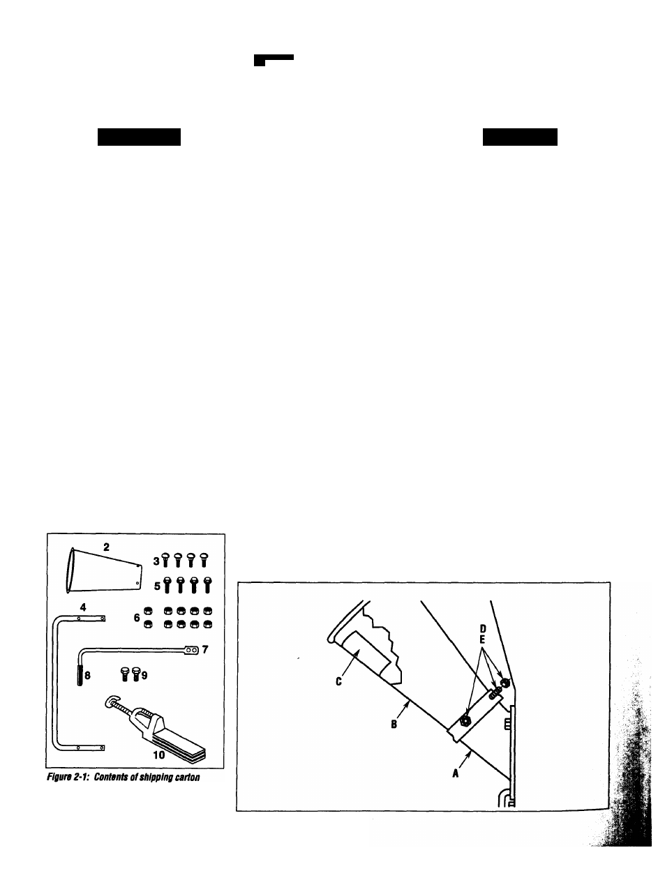
STEP 3: AHACH CHIPPER CHUTE
1. Find the safety message decal (C,
Figure 2-2) located inside the large open
ing of the chipper chute (B).
iMPORTANT:
The chute must be instailed
so that the safety message decal (C) can
be read when the operator looks down into
the chute.
2. Insert the small end of the chipper
chute (B, Figure 2-2) into the chipper
chute mounting base (A) and align the
four square holes in the chipper chute with
the four round holes in the mounting base.
Check that the safety message decal (C) is
positioned as shown in Figure 2-2.
3. Reach inside the chipper chute and
insert four 1/4"-20 x 5/8" round head car
riage bolts (D, Figure 2-2) out through the
four holes. Add 1/4"-20 toplock nuts (E)
and tighten securely.
(shown al reduced sizes).
Figure 2-2: Install chipper chute.