Cylinder assembly service and repair, A warning, Cylinder assembly removal – Troy-Bilt 47330 User Manual
Page 18: Cylinder assembly disassembly, Warning
Attention! The text in this document has been recognized automatically. To view the original document, you can use the "Original mode".
18 Section 5: Maintenance
A
WARNING
Faiture to foitow these instructions can resutt in serious personat injury or property damage.
Before inspecting, cieaning or servicing the machine, shut off engine, wait for ait moving parts to
come to a comptete stop, disconnect spark ptug wire and move wire away from spark ptug.
CYLINDER ASSEMBLY
SERVICE AND REPAIR
A
WARNING
Before performing any maintenance on
the unit, stop the engine, wait for ait
moving parts to stop and disconnect
spark ptug wire. Wear gioves when
working with the cyiinder assembty to
protect against cuts.
Cylinder Assembly Removal
1. Remove the upper clutch lever section
from the lower section by removing the
two screws and nuts.
2. Remove the eight flange screws secur
ing the shredder hopper to the unit.
Remove the hopper.
3. Remove the discharge screen or bar
grate (see
Removing/lnstalling Discharge
Screen or Bar Grate
in Section 4).
Remove the belt cover as described in
Belt Removal/lnstallation
in this Section.
HOLE FOR PUNCH
BEARING
• Tighten In direction of
shott rotetlon (counter
clockwise)
• Loosen egelnst direc
tion of shaft rotation
(clockwise)
SET SCREW-
Figure 5-3
BEARING COLLAR
A
WARNING
Wear sturdy work gioves and bo careful
handling the cylinder assembly. Many
cutting edges on the assembly can
cause severe cuts. Be especially care-
tul near the chipper blade.______
4.
Remove the snap ring that secures the
cylinder pulley to the cylinder assembly.
Carefully note (for later reassembly) the
location of all hardware securing cylinder
pulley to cylinder. Remove the cylinder
pulley.
5. Loosen set screw that secures bearing
locking collar on cylinder shaft (located
under cylinder pulley). Remove the lock
ing collar from the cylinder shaft by turn
ing the collar against the direction of the
shaft rotation. Use a hammer and a punch
to loosen the collar (Figure 5-3).
6. Place a long wooden stick down the
shredder hopper to prevent the cylinder
assembly from rotating. Remove the cap
screw securing the other end of the cylin
der shaft. Remove the remaining washers
and spacers from the cylinder shaft. Note
that there is a felt washer at each end of
the shaft to protect the bearings. Also
note the location of all hardware for
reassembly. Remove the stick from the
.Jiopper.
A
WARNING
Take special care to note the exact or
der and placement of all parts on the
cylinder assembly for reassembly. It is
recommended that the cyiinder pins and
all components be marked before disas
sembly to aid In correct reassembly. If
there are any questions about correct
placement and order of cylinder assem
bly parts, refer to the cylinder assembly
parts breakdown (located in the parts
list). Failure to follow these instruc
tions could result in severe personal
injury or property damage.
NOTE; An assistant will be needed for the
next step.
7. Put on sturdy work gloves and safety
glasses. Hold the cylinder assembly
through the hopper opening. Remove the
six flange screws (keep any washers with
screws) retaining the cylinder shaft bear
ings and the closure plate to the main
frame. The cylinder assembly can now be
lowered out of the unit.
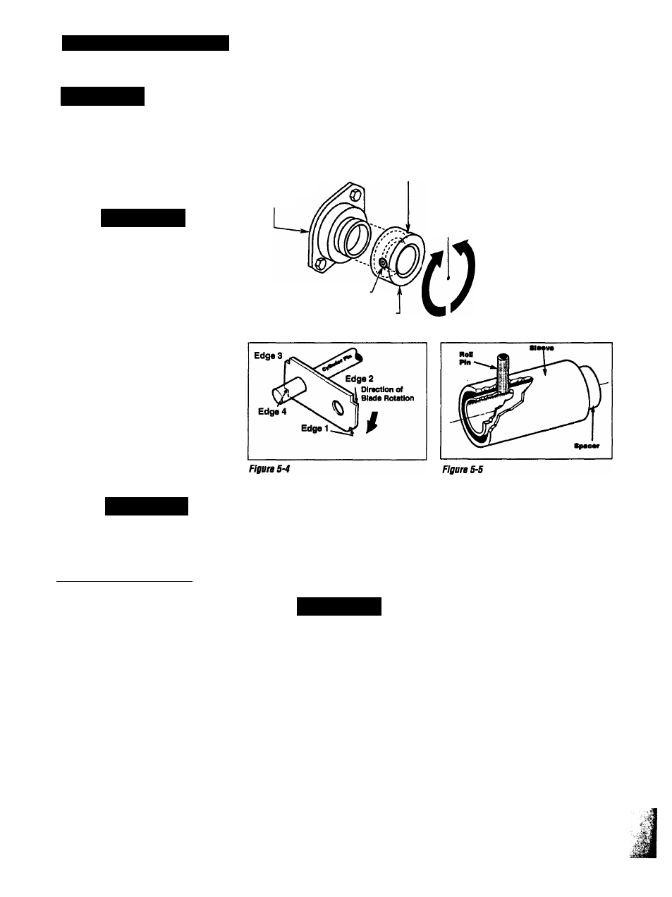
The shredder blades (flails) on the cylinder
assembly can be rotated or flipped if dull
(Figure 5-4). The shredder blades use
only one cutting edge at a time.
Cylinder Assembly Disassembly
NOTE; Roll pins (see Figures 5-5 and
5-5A) secure the three cylinder pins in the
cylinder assembly. The roll pins must be
driven from the assembly with a 5/32*
punch and hammer. The pins will come
out in only one direction through the outer
sleeves (Figure 5-5).
1. Securely clamp the cylinder assembly
by the chipper flywheel in a vise. Position