Chipper blade removal/instalution, A warning, Chipper blade removal/lnstallation – Troy-Bilt 47330 User Manual
Page 20: Cylinder assembly components, Warning, Chipper blade removal/instalution a
Attention! The text in this document has been recognized automatically. To view the original document, you can use the "Original mode".
20 Section 5: Maintenance
'A
A
WARNING
Faiiure to foiiow these instructions can result in serious personal injury or property damage.
Before inspecting, cieaning or servicing the machine, shut off engine, wait for aii moving parts to
come to a compiate stop, disconnect spark piug wire and move wire away from spark piug.
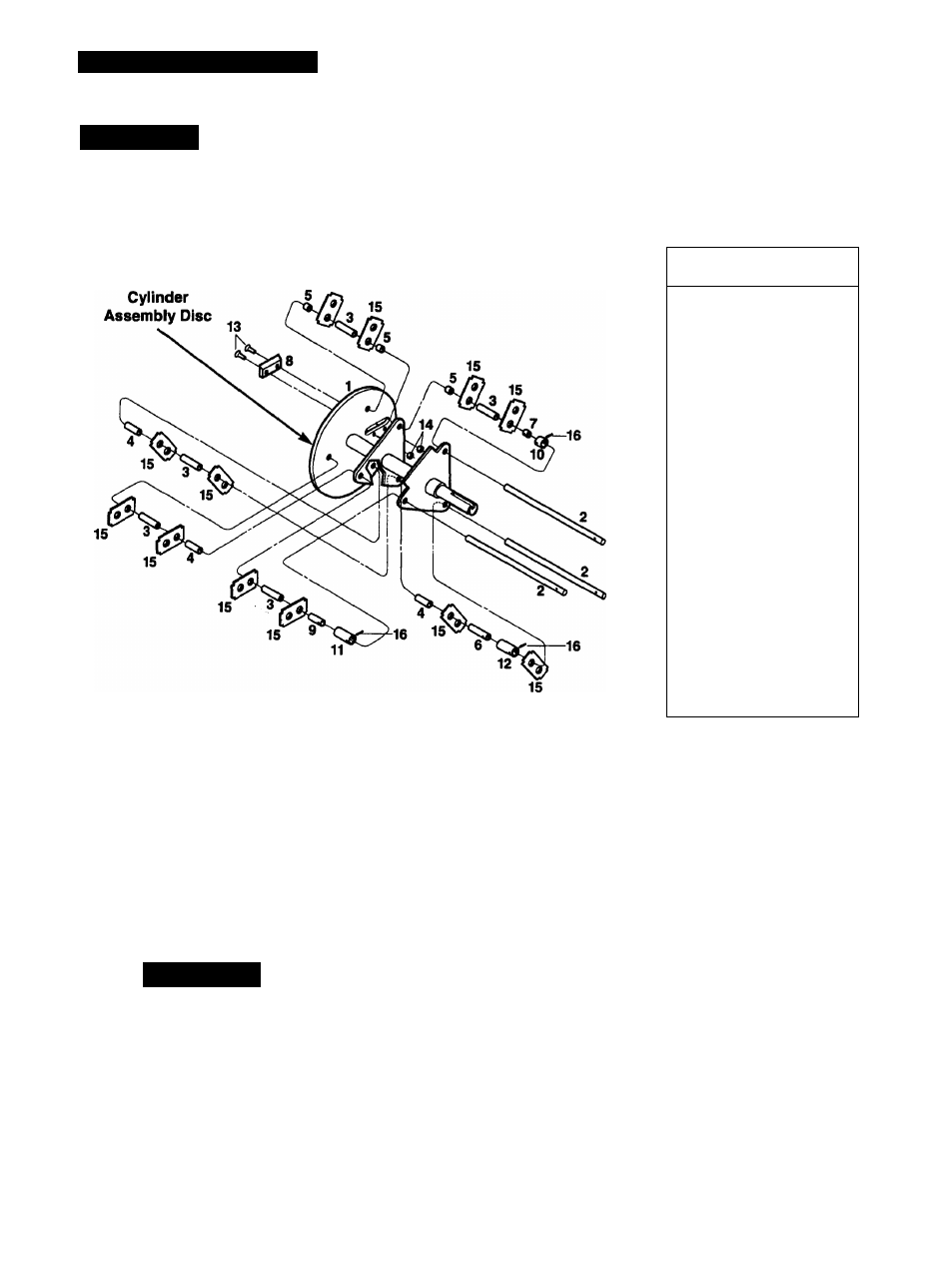
CYLINDER ASSEMBLY COMPONENTS
15
Figure 5-5A
Ref.
No.
Description
1
Cylinder Weldment
2
Pin, Cylinder
3
Spacer, Long, 2'
4
Spacer, Medium, 1-5/16“
5
Spacer, Short, 11/16“
6
Spacer, Long, locking, 2“
7
Spacer, Short, locking,
11/16"
8
Blade, Chipper
9
Spacer, Medium, locking,
1-5/16“
10
Sleeve, Short, outer, 1/2“
11
Sleeve, Medium outer,
1-1/8“
12
Sleeve, Long, outer,
1-3/4“
13
Screw, FI. Csk. Socket Hd.,
1/4“-20x1“
14
Nut, Hex Locking, 1/4“-20
15
Blade, Shredder
16
Pin, Roll, 3/16“
X
3/4“
7. Reinstall the hopper assembly using the
eight flange screws removed in Step 2 of
Cylinder Assembly Removal.
8. Reinstall the upper section of the clutch
lever using the two screws and nuts
removed in Step 1 of
Cylinder Assembly
Removal.
CHIPPER BLADE
REMOVAL/INSTALUTION
A
WARNING
The chipper blade is extremely sharp.
To avoid personal injury, handle the
blade with extreme care during service
or maintenance.
Shut engine off, let all moving parts
stop completely, disconnect spark piug
wire and prevent it from touching spark
plug before performing any mainte
nance on the unit.
The chipper blade should be sharpened or
replaced when the unit no longer cuts as
efficiently as when new.
"Chipper Blade Removal
1. Stop engine and wait for all parts to
come to a complete stop. Disconnect
spark plug wire and secure it away from
spark plug.
2. Lower the front end of the discharge
screen (or remove screen for more work
ing room). Refer to
Removing/lnstalling
Discharge Screen or Bar Grate
in Section
4 for instructions.
3. Remove and save the three flange
screws (A, Figure 5-6) from the base of
the chipper chute and remove the chute.
4. The chipper blade Is extremely sharp
- wear heavy leather gloves when work
ing near it.
5. Wearing gloves, rotate the large round
flywheel carefully until the chipper blade is
exposed in the chipper chute opening.
6. Prevent the flywheel from turning by
wedging the cylinder assembly against the
internal walls of the machine with a sturdy
block of wood.
7. Using a 5/32" hex key wrench and a
7/16“ open-end wrench, reach up inside
the shredder chamber and remove the two
nuts and socket head screws from the
chipper blade (see Figure 5-7). Remove
the chipper blade.
8. If a blade is dull or nicked, sharpen it at
a 45“ angle. See inset. Figure 5-7. If you
don’t have sharpening experience and the
proper equipment, take the blade to a pro
fessional sharpening service.
If the blade is cracked or damaged,
throw it awayl Never use a cracked
blade since pieces of the blade could
break off and cause personal injury.