Ariens SNO- THROS 932007 User Manual
Page 6
Attention! The text in this document has been recognized automatically. To view the original document, you can use the "Original mode".
CHUTE CRANK ADJUSTMENT
REPLACEMENT OF THE BLOWER DRIVE BELT
In the event the chute crank fails to rotate freely, loosen the
nut securing the worm clevis to the bracket. This hole in the
bracket is slotted to permit adjustment. Position the worm
so there is a little clearance between worm and the gear
teeth on the blower. Tighten the nut. Rotate the discharge
chute through its full travel to see that it turns easily. Re
adjust if required. Lubricate as described under LUBRI
CATION for smooth operation.
BELT REPLACEMENT
CAUTION:
SINCE REPLACING THE BEL TS WILL INVOL VE TURNING
THE ENGINE OVER WITH THE STARTER, THE SPARK
PLUG WIRE MUST BE DISCONNECTED DURING THIS
PROCEDURE.
The drive belt and the attachment drive belt are both ac
cessible by tipping apart the blower housing and tractor as
follows:
1. Remove the nut and lockwashers holding the worm clevis on
the bracket. Remove the chute crank by sliding it back in
the bracket and out of the way.
2. Remove the two flanged whiziock screws securing the belt
guard to the tractor. Remove the belt guard.
3. Remove the top cap screws and loosen the lower cap screws
on each side that secures the blower housing to the frame.
As the blower housing and tractor are tipped apart, roll
finger. This can be easily done by pulling the recoil
starter rope to rotate the engine sheave. With the belt dis
connected, the blower housing may then be tipped from
the frame.
TRACTION IDLER
y'
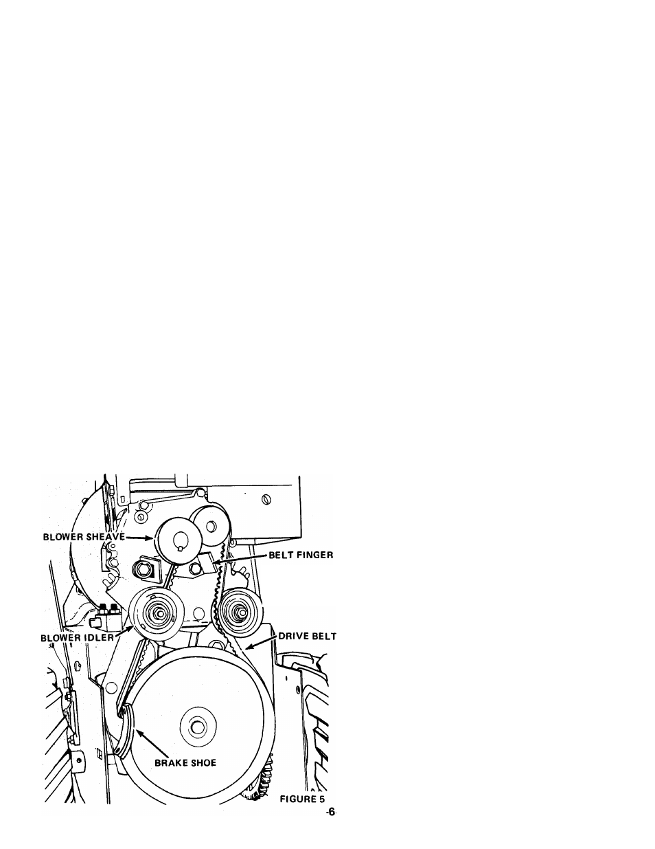
The blower drive belt remains on the sheave on the blower
housing. Place the new belt on the sheave. Hold it in position
on the sheave as the blower is tipped into position on the^^^^
tractor. Be sure the brake shoe seats on the belt as the units,
1'
are tipped together. Once assembled, roll the blower belt on to
the engine sheave and position the idler on the outside of
the belt.
REPLACEMENT OF TRACTION DRIVE BELT
With the blower and tractor tipped apart, pull the idler
away from the drive belt and remove belt from around
the lower sheave and engine sheave. Install the new belt on
the engine sheave and lower sheave. Then reposition the
idler back into position on the outside of the drive belt.
With the belts in position and the idler in place, check the
belt alignment. The engine sheave and the tractor sheave
must align with one another. If the sheaves are not properly
aligned, loosen the setscrews on the engine sheave and align
the sheaves. Retighten the setscrews.
REPLACEMENT OF BLOWER HOUSING
1. Tip the blower and tractor together. Hold the blower drive
belt up as the units are tipped together. Be sure the blower
brake shoe seats on the blower sheave. Secure with the two
cap screws into the frame.
2.
Roll the blower belt on to the engine sheave. Pull the
recoil starter rope to turn the engine sheave and roll the
belt into place under the belt finger.
3.
Check the belt finger spacing. There should be 1/8 inch
clearance between the belt finger and belt with the blower
clutch engaged. Readjust the belt finger if required.
4. Check the sheave alignment with the blower belt in place.
Readjust as required to align the sheaves. It may be neces
sary to tip the blower housing away from the tractor to
gain access to the blower sheave.
5. Replace the belt guard and chute crank assemblies. Re
adjust the chute crank as described in the paragraph above.
Replace the spark plug wire.
REPLACEMENT OF FRICTION WHEEL
1.
Tip the machine up on the blower housing and brace
securely. Remove two cap screws at back of frame securing
the bottom cover and loosen two cap screws at front
frame sides and remove the cover.
2. Remove the four whiziock nuts holding the bearing flange
on the right hand side of the frame. Remove the bearing
flange and carriage bolts.
3.
Remove the hairpin cotter from the traction clutch rod.
Pull this rod from the clutch fork arm and tip it up and out
of the way.
4. Slide the friction wheel assembly and hex shaft to the right
until the left end of the hex shaft comes free of the left
bearing. Then slip the whole assembly back to the left and
pull it forward out of the frame.