Dealer set up and pre-service – Ariens SNO- THROS 932007 User Manual
Page 12
Attention! The text in this document has been recognized automatically. To view the original document, you can use the "Original mode".
DEALER SET UP AND PRE-SERVICE
1. GENERAL
The unit is shipped with tractor and snow head assembled.
The handlebars are assembled but must be installed on the
tractor and the clutch rods and chute crank installed.
2. HANDLEBAR INSTALLATION
The handlebars are attached to the holes in the side of the
frame. Install a 59022 cap screw (3/4" long), a 64123 flat
washer and 63003 lockwasher in the lower hole on each side
of the frame. Do not tighten. The end of the handlebars are
slotted. Slip these slotted ends over the cap screws just in
stalled. Position the handlebars under the flat washer. Insert
a 59069 cap screw (1-1/4" long), 64123 Washer and 63003
lockwasher through each of the upper holes in the handlebars.
Hold the handlebars up in a comfortable position and tighten
all hardware.
3. THROTTLE CONTROL
Models 932001 and 932004 have the throttle controls lo
cated on the engine. Models 932006 and 932007 have the
throttle control installed on the handlebar panel. Run the
throttle cable along the inside of the left handlebar and up
under the heater box. Connect the bent end of the wire to the
throttle arm of the carburetor. Place the throttle in the fast
position, push the throttle arm up, and clamp the cable with
the screw and clamp "on the engine. Check by moving the
throttle back and forth. Throttle arm should move top to
bottom of travel. Install 69099 clamp to secure throttle
cable to handlebars.
4. WIRING HARNESS
The wiring harness is supplied attached to the engine. Run
this harness from the engine, up the left handlebar, to the
key switch. Connect wire to terminals on the key switch.
Secure the wiring harness to the left handlebar with throttle
control clamp (69099).
5. TRACTION CLWTGH ROD
The traction clutch rod is shipped loose in the carton. To
install the rod, place the speed selector in third speed; Insert
the bent end of the clutch rod into the hole in the clutch
handle on the left handlebar. Insert the straight end of the
clutch rod into the hole in the rod adapter in the clutch
bracket at the left rear of the frame. Hold the clutch handle
all the way down; raise the clutch bracket up to 1/16 inch of
the frame; now tighten the rod in place with the setscrew in
the rod adapter.
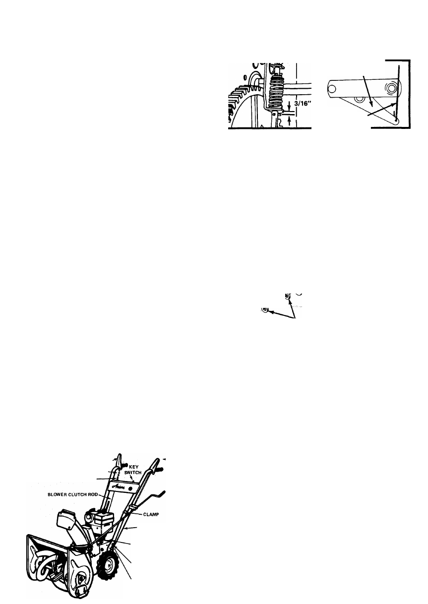
This adjustment can be checked by removing the bottom
cover. With the clutch handle fully depressed the clearance
between the roll pin and the bracket should be 3/16 inch.
See Figure 11. Loosen the setscrew and readjust if required.
6. BLOWER CLUTCH ROD
Install the blower clutch rod by hooking the end of the
clutch rod up through the hole in the blower clutch
lever on the right rear of the frame, see Figure 12. Connect the
BLOWER CLUTCH
CHAIN .
SPRING-
TRACTION
CLUTCH
FIGURE 10
■TRACTION
CLUTCH ROD
WIRE HARNESS
'1-1/4" CAPSCREW
IN UPPER HOLE
3/4" CAPSCREW
IN LOWER HOLE
spring end of the clutch rod to a link in the chain on the
handle. Select a link that will allow the spring to extend
slightly when the clutch handle is fully depressed.
BLOWER
CLUTCH LEVER
BLOWER
CLUTCH ROD
FIGURE 11
7. CHUTE CONTROL CRANK
FIGURE 12
The chute control crank Is shipped fully assembled and in
place in the bracket. Install as follows: Bolt the crank clamp
in place on the left handlebar. See Figure 1.
Position the worm clevis on the bracket on the blower
housing. Place external tooth lockwasher between worm
clevis and bracket. Adjust in slot so that there is a little
clearance between worm and gear teeth on blower collar.
Secure the worm clevis with the carriage bolt (already in
place on the clevis). Use a lockwasher (63023) and a 5/16-18
nut (65015) under the bracket. See Figures 1 and 2.
Rotate the discharge chute through its full travel to see
that it turns easily. Readjust the position of the worm clevis,
if required.
rla
STIC
WASHER
\ CARRIAGE BOLT
ADJUST FOR PROPER
DEFLECTOR TENSION
^
WAVE WASHER
?
1.0CKNÜT
ii;
ER
CAR
FLAT WASHERS
FIGURE 13
EXTERNAL
TOOTH
LOCKWASHER
8. DEFLECTOR
The deflector is shipped in place on the discharge chute but
must be raised into operating position. Remove the locking
hardware from the discharge chute. Raise the deflector up
into position. Re-install the hardware as shown on Figure 13.
Adjust the nut to apply sufficient tension so the deflector can
be easily moved by hand but will still hold position when
blowing snow.
9. BLOWER GEAR CASE
The blower gear case is factory lubricated and should re
quire no lubrication by the dealer. Full instructions for
checking are given in the LUBRICATION section of this
manual. Page 7.
10. ENGINE
Before starting engine, fill the crankcase with Ariens
Sno-Thro oil 5W-20 for snow blower operation below 40°
F. Use Ariens Gard-N-Oil 10W-30 for operation above 40°
F. Refer to Engine Owners Manual for appropriate substitutes.
-
12
-
11. TIRE PRESSURE
Models 932004, 932006 and 932007 are equipped with
pneumatic tires that have been over inflated for shipping
purposes. Reduce pressure to 12 to 20 PSI before operating.
Tire pressure of 20 PSI is recommended for use with tire
chains.
DEALER MUST MAKE SURE ALL SAFETY DEVICES AND
GUARDS ARE IN POSITION AND OPERATING PROP
ERLY. DEALER MUST INSTRUCT THE CUSTOMER ON
SAFETY PRECAUTIONS, OPERATING, CARE AND MAIN
TENANCE. FILL OUT PREWARRANTY REGISTRATION
AND MAIL TO ARIENS COMPANY.
{