Operating instructions – Ariens Sno-Thro ST4-65R User Manual
Page 4
Attention! The text in this document has been recognized automatically. To view the original document, you can use the "Original mode".
OPERATING INSTRUCTIONS
1. ENGINE
Complete instructions for the operation, lubri
cation, and proper care of the engine will be found
on the instruction plate attached to the engine fan
housing and in the maniifacturer’s instruction book
packed with the engine. Do not attempt to start the
engine before following the manufacturer's recom
mendations for servicing the engine.
2. TRACTOR CLUTCH
a. The clutch operating handle mounted on the
left handle bar serves to disengage the clutch so
that the shift control lever may be moved to any one
of the four forward speeds or reverse position.
b. When the clutch operating handle is squeezed
together, the shift control lever may be moved to the
desired position. Releasing the handle will cause
the machine to move in the direction and at the speed
selected. Once the tractor is is motion, it is pos
sible, without using the clutch, to shift to a higher
or lower speed range. However, the clutch must be
used when moving the shift control lever into neu
tral or reverse.
c. A locking device is provided on the clutch
operating handle to hold the handle in the non
operating position. The lock is released by a light
squeeze on the handle.
3. SHIFT CONTROL LEVER
a. The shift control lever mounted on the right
handle bar governs the speed and direction of the
tractor.
b. To move the shift control lever to a selected
position, squeeze the tractor clutch operating handle
together, depress the button on the center of the shift
control lever knob and move the lever.
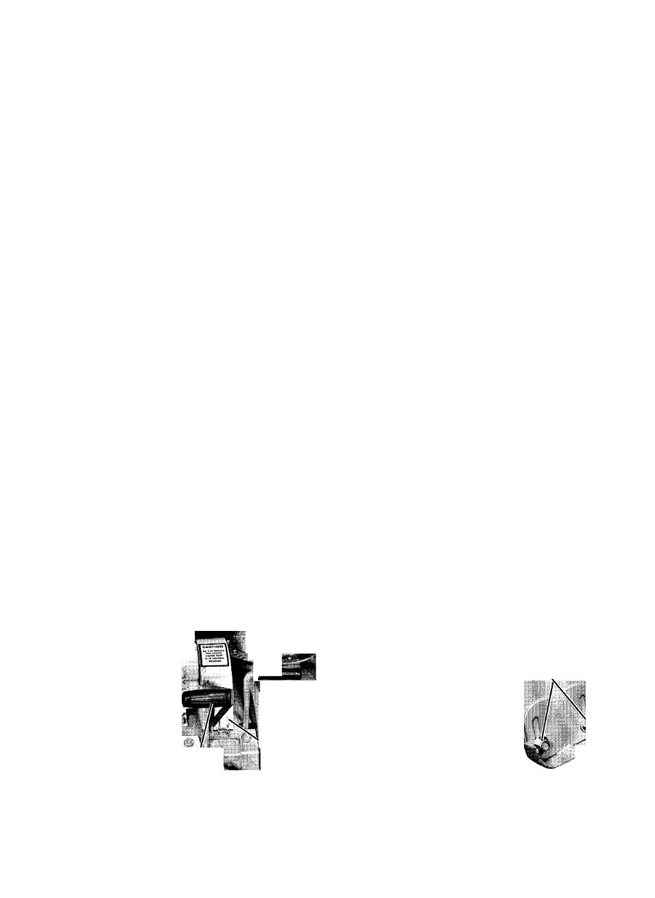
4. ENGINE CLUTCH
a.
The engine clutch is controlled by a lever
mounted on the right hand side of the unit (figure 3)
just forward of the engine.
^
-
w
—
*
o 0 " -
' < & D R A I N
SNO-THRO
CLUTCH
L A T C H
ENGINE
CLUTCH
Figure 3
b. When the clutch control lever is pulled up,
the idler pulley bears against the drive belt causing
the engine to drive the tractor transmission.
c. When the clutch control lever is pushed down,
the idler pulley moves away from the drive belt,
loosening the belt and the transmission stops.
5. SNO-THRO CLUTCH
a. The Sno-Thro clutch is controlled by a lever
at the rear of the Sno-Thro blower housing (figure 3).
b. To start the Sno-Thro auger and blower, start
the engine, place the Sno-Thro clutch in the IN posi
tion (clockwise) and engage the engine clutch on the
tractor.
c. To stop the Sno-Thro auger and blower, dis
engage the engine clutch on the tractor and place the
Sno-Thro clutch in the OUT position (counterclock
wise).
d. The tractor may be used to move the unit with
the Sno-Thro auger and blower stopped by engaging
the tractor clutch while leaving the Sno-Thro clutch
in the OUT position.
6. THROTTLE CONTROL
The throttle control lever controls the speed of
the engine and therefore, in conjunction with the shift
control lever, the speed of the machine. Moving the
lever toward "F" increases engine speed and moving
it toward "S" decreases speed. Moving the lever to
the STOP position will stop the engine. ALWAYS
MOVE THE THROTTLE LEVER TO "PARK" AFTER
ENGINE HAS STOPPED.
7. CHOKE
A manual choke is provided which is operated by
a lever projecting from the carburetor cover on the
left hand side of the engine. The lever can be placed
in any one of four detent positions. Moving the lever
toward the rear of the machine places it in the FULL
CHOKE position. As it is moved forward, it will
pass through the 3/4 CHOKE and 1/2 CHOKE posi
tions to the NO CHOKE position fully forward.
8. RUNNERS
a. An adjustable runner is
provided on each end of the
blower
housing
(figure
4).
Raising or lowering these run
ners controls the distance the
scraper blade is held above
the surface being plowed. Ad
justment is accomplished by
loosening the two nuts on each
of the rimners to the desired
position and retightening the
nuts.
LOCKNUTS
\
RUNNERS
Figure 4