Assembly – Ariens Sno-Thro ST4-65R User Manual
Page 2
Attention! The text in this document has been recognized automatically. To view the original document, you can use the "Original mode".
SAFE SNOW REMOVAL IS NO ACCIDENT
Improper use of snow removal equipment on the
part of the operator can result in injury. To reduce
this possibility, give complete and undivided atten
tion to the job at hand.
Protect Yourself and Others by Following These
Safety Tips
1.
Stop motor before cleaning discharge, removing
obstacles, making adjustments, or when leaving
operating position.
2.
Never direct discharge at bystanders nor allow
anyone in front of machine — debris may be
hidden in the snow.
3. Keep children and pets a safe distance away.
4.
Do not allow children to operate machine nor
allow adults to operate it without proper in
struction.
5.
Adjust height to clear gravel or crushed rock
surface.
6.
Exercise caution to avoid slipping or falling,
especially when operating in reverse.
7. Know the controls and how to stop quickly —
read the owner’s manual.
8. Handle gasoline with care — it is highly flam
mable.
A. Use approved gasoline container.
B. Never add gasoline to a running engine —
fill tank out of doors and wipe up spilled
gasoline.
C. Replace gasoline cap securely.
D. Open doors if engine is run in garage —
exhaust gases are dangerous.
9.
Disengage all clutches and shift into neutral be
fore starting motor. Keep hands, feet, and
clothing away from power driven parts.
10. Use a grounded three wire extension cord for
all plug-in electric units.
11. Keep machine in good operating condition and
keep safety devices in place.
ASSEMBLY
1. GENERAL
When impacking, be sure to remove all loose
items from the carton.
2. HANDLE BARS
a. Place the holes in the flat section of the
lower handle bars over the studs projecting from
the frame on each side of the engine.
b. Place a lockwasher and nut on each stud but
do not tighten.
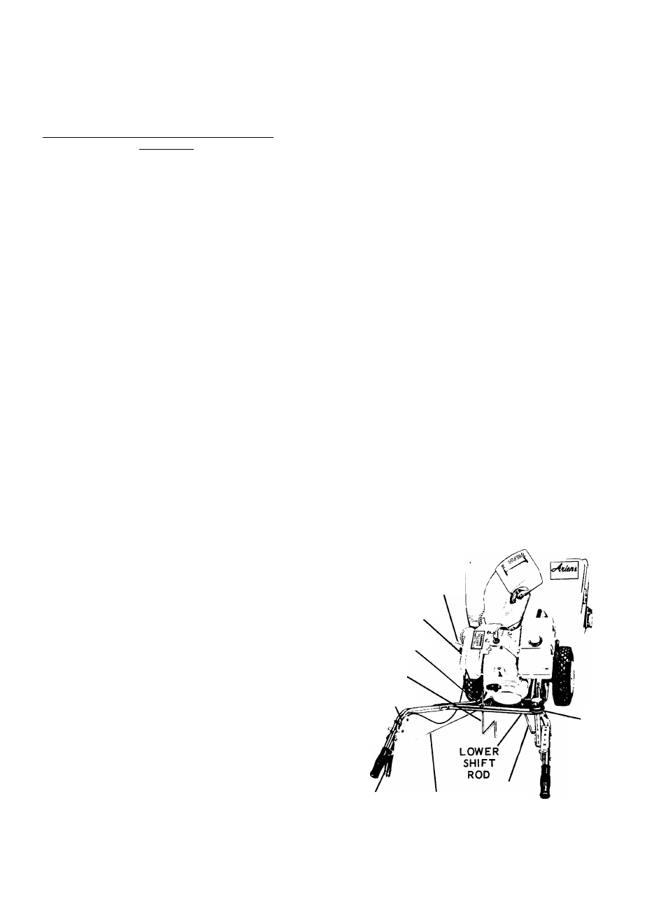
c. Remove the four bolts from the lower portion
of the upper handle bar and slide the upper handle
bar in place between the curved portions of the
lower handle bars (figure 1).
d. Replace the bolts in the top hole of the lower
handle bar and the matching hole in the upper handle
bar. Fasten with locknut.
e. Hook the bent portion of the nameplate panel
over the lower handle bar and slide it up until the
holes in the panel line up with the lower holes in the
lower handle bar. Fasten in place with bolts and
locknuts.
f. Tighten the nuts holding the lower handle bar
to the frame.
3. SHIFT CONTROL
Position the shift control (figure 1) on the In
side of the handle bars on the right hand side so that
the holes in the control line up with the holes in the
handle bar. Fasten the control to the handle bar with
two hex head cap screws and lockwashers (figure 1).
CHOKE
PRIMER
ROD
HANGER
CHUTE
CONTROL
CRANK
THROTTLE
LOCK
PIN\
CLUTCH
CLUTCH
HANDLE ROD
UPPER
SHIFT
ROD
SHIFT
CONTROL
LEVER
Figure 1