Electrolyte level, Charging, Adjustments – Ariens SNO-THRO 924326-ST1336LE User Manual
Page 17: Discharge chute deflector, Deflector remote, Runners, Scraper blade, Chute crank
Attention! The text in this document has been recognized automatically. To view the original document, you can use the "Original mode".
Electrolyte Level
Every 25 hours or each week check electrolyte level of
each cell by removing caps one at a time. The electrolyte
level should be at level indicator. Use distilled water to fill
each ceil if needed.
IMPORTANT: When distilled water is added to battery
during freezing weather, it must be charged to mix water
with electrolyte or water will remain at top and freeze.
Charging
Place unit on a level surface, shut off engine and open
battery compartment (Figure 5).
1. Disconnect negative {-) cable first, then positive (+)
cable.
2. Loosen wing nut and remove battery.
3. Place Battery on bench or other well ventilated place
where electrolyte spill will not create damage.
4. Remove caps and fill each cell to level indicated with
electrolyte at 1.265 specific gravity and SO'^F (27°C).
5. Let battery stand for one half hour.
6. Check electrolyte level and add more if necessary.
7. Connect positive (+) lead of charger to positive (+)
terminal, and negative {-) lead to negative (-) terminal.
8. Charge the battery at two and a half amps for ten
hours or until all cells are gassing freely and the
specific gravity is constant over three 30 minute
intervals.
9. Immediately after charging, check electrolyte level. If
low, add distilled water to bring cell up to required level.
10. Replace caps finger tight, wash off and dry battery.
11. Reinstall battery into unit and connect positive (+)
cable first, then negative {-) cable.
A
djustments
Discharge Chute Deflector
To adjust, loosen then retighten hardware to desired
deflector drag force (Figure 5).
Deflector Remote
Adjust as required at clevis end and/or cap pivot cable
end fitting.
Runners
Runners should be adjusted (Figure 12) as conditions
require. Raising or lowering runners controls distance
scraper blade (auger/impeller housing) is held above
surface being cleared.
1. Position unit on a hard, flat, smooth level surface.
2. Adjust runners by inserting a spacer of desired
thickness under center of scraper blade, loosen
hardware, slide runners to flat surface. Allow 1/8"
(3mm) between scraper blade and hard smooth
surfaces. Allow 1-1/4" (30mm) between scraper
blade and uneven surface(s). Retighten hardware.
2. Runner Hardware
Figure 12
NOTE; Keep housing level by adjusting runners equally.
Uneven runners make unit difficult to steer and results in
uneven clearing.
Scraper Blade
IMPORTANT: Damage to auger/impeller housing wilt
result if blade wears down too far.
Scraper blade is adjustable to compensate for wear.
To adjust scraper blade:
1. Tip unit back onto handlebar, support housing and
loosen nuts retaining blade. With runners adjusted to
their full up position, reposition scraper blade down,
flush with runners, and tighten lock nuts.
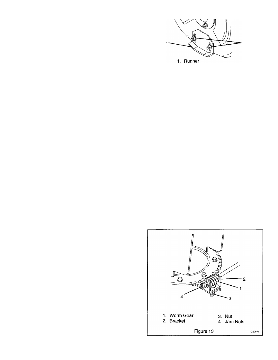
Chute Crank
Smooth and easy rotation of properly lubricated chute
with crank (without binding) is obtained by adjusting
clearance between worm (Figure 13) and discharge
chute gear teeth.
1. To adjust, loosen nut on bracket supporting worm,
position worm to fully engage (without binding), gear
teeth on discharge chute and tighten nut.
To prevent discharge chute from rotating by Itself when
unit is being operated, tighten jam nuts on end of crank
rod to put increased tension on worm gear.
Rev. 9/98
Ariens® 924 Sno-Thro
13