Traction drive belt, Attachment drive belt, Traction drive belt attachment drive belt – Ariens SNO-THRO 924326-ST1336LE User Manual
Page 14: Atitniliie
Attention! The text in this document has been recognized automatically. To view the original document, you can use the "Original mode".
T
raction
D
rive
B
elt
Atitniliie
nt rtQPn
**
ROTATING PARTS can cut off body
parts. Keep hands and feet away.
Loose clothing, long hair or scarves can
get caught in rotating parts and cause
death or serious injury.______________
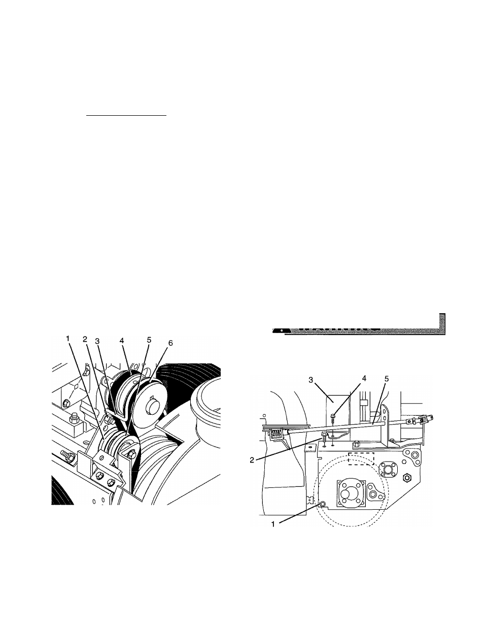
NOTE: Housing and frame must be tipped apart and
attachment drive belt removed from engine sheave in
order to change traction drive belt (Figure 6).
1. Pull idler away from belt and remove belt from idler
pulley, engine and driven pulley (it may be
necessary to turn engine pulley using rewind
starter).
2. Rotate belt fingers out and away from belt and pulley
by removing one cap screw and loosening the other.
IMPORTANT: Use care when rotating the belt fingers to
prevent deformation of parts.
NOTE: To gain clearance engage traction clutch and if
necessary pull back attachment idler arm clevis pin.
3. Replace traction drive belt and belt fingers in reverse
order making sure pulleys align. If alignment is
necessary, loosen engine pulley set screws,
reposition pulley and retighten set screws. Check
alignment of attachment driven pulley and align if
necessary.
1. Traction Belt Idler
2. Cap Screw
3. Beit Finger
4. Attachment Belt Idler
5. Traction Drive Belt
6. Attachment Drive Belt
Figure 6
A
ttachment
D
rive
B
elt
For Attachment Drive Belt Replacement (Figure 7):
1. Shut off engine and allow to cool completely.
2. Remove two screws securing belt guard to unit and
remove belt guard cover.
3. Remove hardware fastening worm gear bracket to
housing (Figure 13).
4. Loosen cap scews and carefully rotate belt fingers
out and away from belt and pulley (Figure 6).
Remove attachment drive belt (Figure 7) from engine
pulley (it may be necessary to turn engine puiley
using rewind starter).
IMPORTANT: To avoid bending bottom cover, when
tipping unit apart, support handlebars firmly or tip unit up
on housing and remove bottom cover by removing four
cap screws before separating unit.
5. Separate housing from unit. Remove cap screws
securing housing to frame (one on each side). Tip
housing and frame apart on pivot pin.
6. Remove attachment drive belt from sheave (hold
brake away from belt).
7. Replace attachment drive belt in reverse order
making sure sheaves align. If alignment is
necessary, loosen attachment sheave set screws,
reposition sheave and retighten set screws.
8. Replace worm gear bracket and adjust chute crank.
L9___________ ■ ■■
IMPELLER BRAKE MUST DISENGAGE when clutch
is engaged. Brake must be at least 1/16" (1,6 mm) to
1/8" (3,2 mm) minimum from belt when disengaged.
1. Pivot Pin
4. Bolt
2. Housing Cap Screws 5. Chute Crank Rod
3. Beit Guard Cover
Figure 7
C
1 0
Ariens® 924 Sno-Thro
Rev. 9/98