Husqvarna HO1997 1018467-97 User Manual
Page 9
Attention! The text in this document has been recognized automatically. To view the original document, you can use the "Original mode".
11
12
.
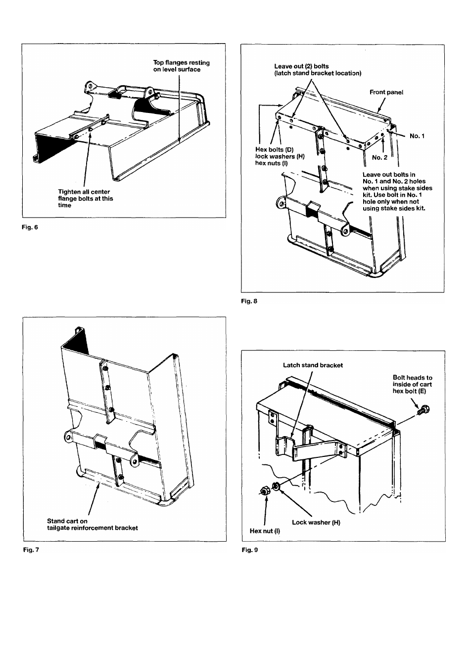
Place cart down, so that it rests on top flange, as shown in
figure 6. Tighten bolts in center flanges, as stated in
step 4.
Lift the cart up and stand on tailgate reinforcement bracket
and proceed with assembly steps 13 through 21. See figure 7.
13. Assembie front panei to open end of cart body, using
1
/
4
"x
1/2" (6 mmx12 mm) hex bolts (D), lock washers (H) and hex
nuts (I). Bolt heads to inside of cart. See figure 8.
N.B. Do not assemble bolts in No. 1 or No. 2 holes when using op
tional stake sides kit (each side). See figure 8.
14.
15.
Assembie latch stand bracket using four 1/4"x5/8" (6 mmx
16 mm) hex bolts (E), lock washers (H) and hex nuts (I). See
figure 9.
Assemble two front top corner caps and two bolts in top
flanges through tailgate reinforcement bracket using 1/4" x
1/2" (6x12 mm) hex bolts (D), lock washers (H) and hex nuts
(I). See figure 10.
16. Assemble axle and drawbar tongue to wheel support keeping
open side of tongue facing down. Fasten axle to wheel sup
port or axle brackets, using 1/4"x11/2" (6 x 40mm) long hex
bolts (G) lock washers (H) and hex nuts (I). See figure 11.
CAUTION! It may be necessary to block cart in upright position
to prevent tipping when instaliing wheels.
10