Husqvarna HO1997 1018467-97 User Manual
Page 10
Attention! The text in this document has been recognized automatically. To view the original document, you can use the "Original mode".
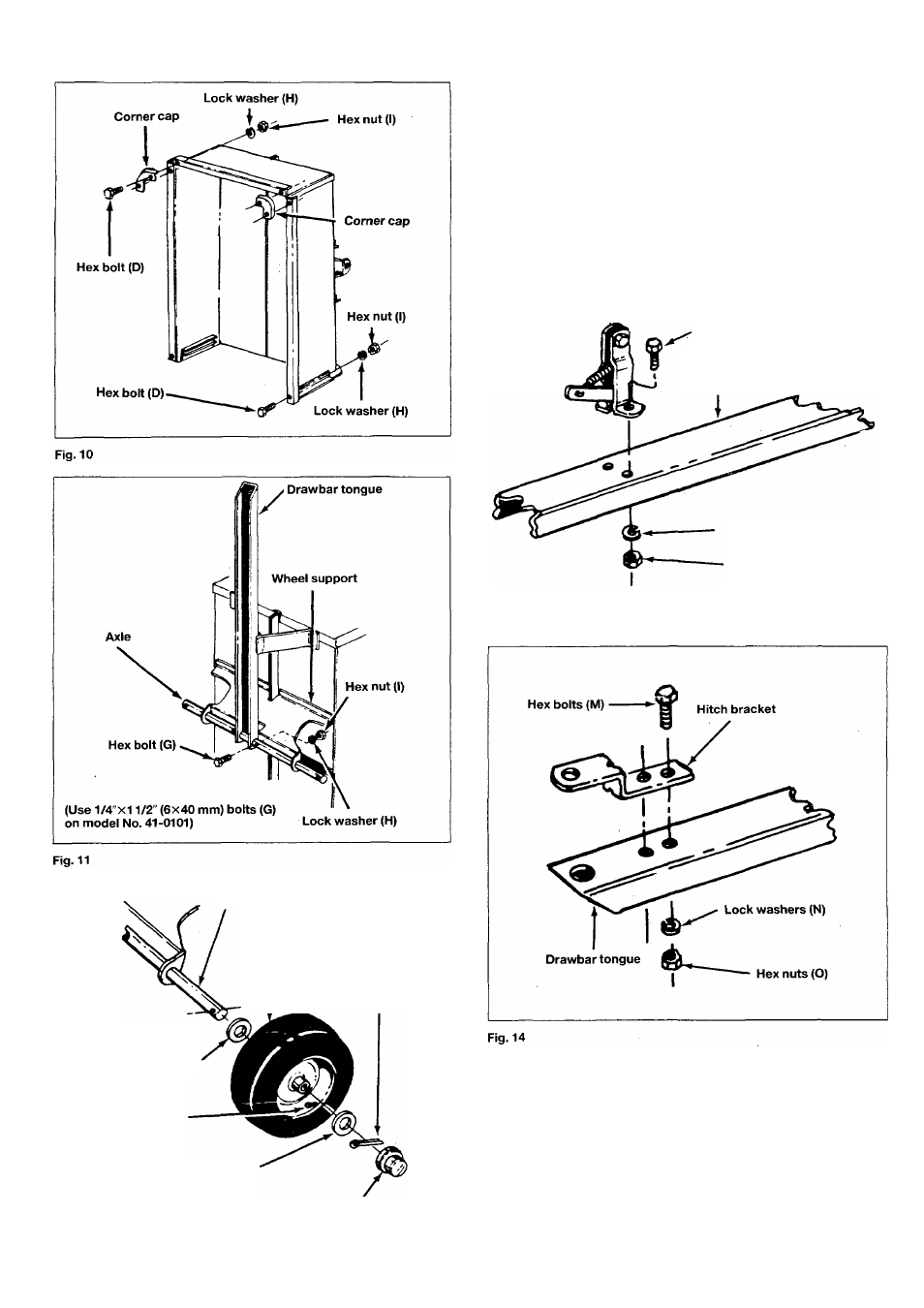
Axle
Wheel
Cotter key (A)
Flat washer (B)
Valve stem
(outside)
Flat washer (B)
Hub cap (C)
17. Assemble large diameter flat washer (B), wheel, another flat
washer (B), cotter key (A) and hub cap (C) to each axle end.
N.B. Position valve stem to outside when installing wheels on axle.
See figure 12.
18. Assemble latch lock sub-assembly to draw bartongue using
1/4"x5/8 (6x16 mm) long hex bolt (E), lock washers (H) and
hex nuts (I). See figure 13.
Latch lock sub-assembly
Hex bolt (E)
Drawbar tongue
Lock washer (H)
Hex nut (I)
Fig. 13
19. Assemble hitch bracket to drawbar tongue, using 3/8”x1"
(10x25 mm) long hex bolts (M),lock washers (N) and hex nuts
(O). See figure 14.
20. Lower the cart assembly to rest on wheels. This completes
the cart assembly. Be sure to read safety rules and operating
instructions before using your new utility cart.
Fig. 12
11