Speed control bell crank, Adjustments (continued) – Ariens 911 User Manual
Page 24
Attention! The text in this document has been recognized automatically. To view the original document, you can use the "Original mode".
Adjustments (Continued)
Drive Wheel
(self propelled model)
•
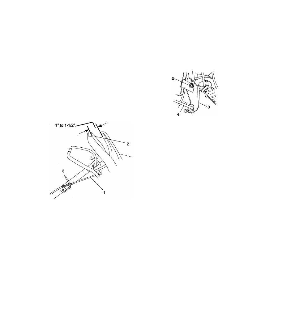
When the Wheel Drive Control is squeezed
toward the handlebar the extension spring,
located at the bottom end of the traction cable,
must start to extend when the control is between
1" and 1 -1/2" away from the handlebar. To
check, squeeze the Wheel Drive Control toward
the handlebar until the spring starts to open.
•
Measure the distance between the Wheel Drive
Control and handlebar at the handlebar
indentation.
•
To obtain the proper adjustment turn the cable
nuts at either the handlebar end or the bottom
end of the traction cable. Tighten the nuts
against the bracket to lock in position.
Speed Control Bell Crank
• To adjust, remove cover, fully compress the
helical spring lockwashers with lock nut and then
back lock nut off one half turn. Align notch in
L.H. side of cover with bolt and secure with knob.
1.
Lock Nut
2.
Helical Spring Lockwashers
3.
Speed Control Bell Crank
4.
Speed Control Rod
Figure 15: Speed Control Bell Crank
1.
Traction Cable
2.
Handlebar Indentation
3.
Cable Nuts
4.
Wheel Drive Control
Figure 14: Wheel Drive Control
22