Adjustments, Handlebar, Engine/blade control – Ariens 911 User Manual
Page 23
Attention! The text in this document has been recognized automatically. To view the original document, you can use the "Original mode".
Adjustments
A
A
WARNING. Stop engine, wait for moving
parts to stop and remove wire form
spark plug (keep wire away from plug to
prevent accidental starting) before
attempting any adjustment procedures.
CAUTION: DO NOT change engine
governor setting or over speed engine.
"Operate engine at the governed no
load speed recommended by the Ariens
Company only." DO NOT exceed this
speed as personal injury may result.
Handlebar
•
Holes in handlebar braces provide four height
positions, a service and (except on professional
models 911065 and 911317) a storage position.
•
To adjust to a safe comfortable operating height,
use one of four hole positions; 1,2,3, or 4 in order
of increasing height, in brace on both sides of
mower and place pin through hole in brace. (On
professional models 911065 and 911317) use
hole positions 1 & 3,1 & 4, 2 & 3 or 2 & 4.)
Refer to illustration.
•
To place handlebar into the handlebar service
position, remove braces from pins, rotate
handlebar forward and place pins into holes of
braces. See Figures 6 and 12.
•
For storage, remove braces from pins, rotate
handlebar forward and place pins into holes
further up on braces.
NOTE: Nuts and bolts replace pins on Professional
models.
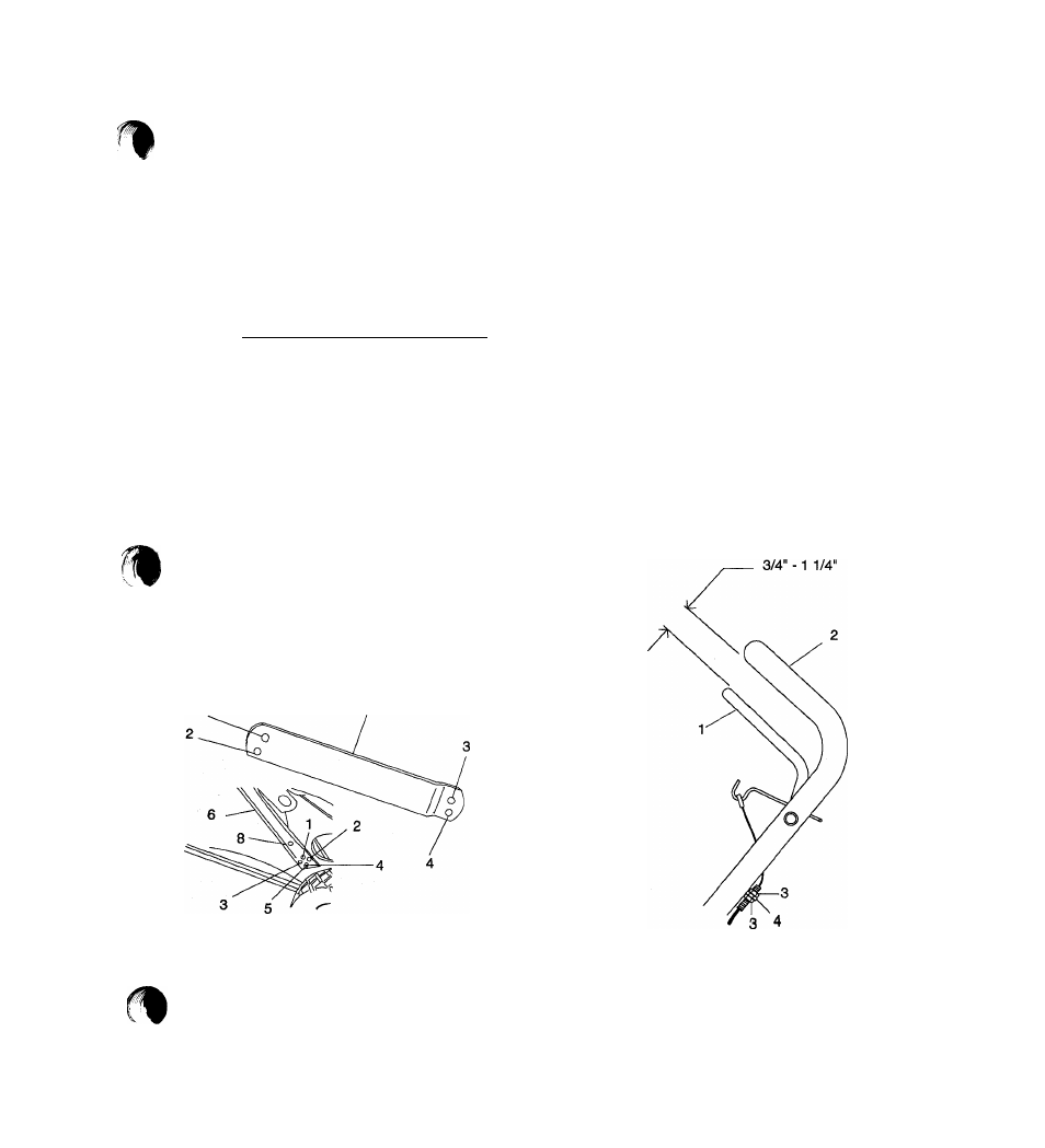
Engine/Blade Control
•
Engine Control must stop engine ignition, at a
point 3/4”-1 1/4” from handlebar as control is
released. To check, start engine and slowly
release Control until engine stops firing.
•
Measure distance between handlebar and control
at the point that engine stopped firing.
•
Turn cable nuts at handlebar mount clockwise if
measurement is more than 11/4" or
counterclockwise if measurement is less than ^
3/4". Turn nuts against mount to lock in position.
1.
Hole No. 1
5.
Pin
1.
Engine Control
2.
Hole No. 2
6.
Brace
2.
Handlebar
3.
Hole No. 3
7.
Professional Brace
3.
Cable Nuts
4.
Hole No. 4
8.
Storage Position
4.
Mount
Figure 12: Handlebar Height
Figure 13: Engine Control
21