Replacement parts - figure 2 – Troy-Bilt 12157 User Manual
Page 22
Attention! The text in this document has been recognized automatically. To view the original document, you can use the "Original mode".
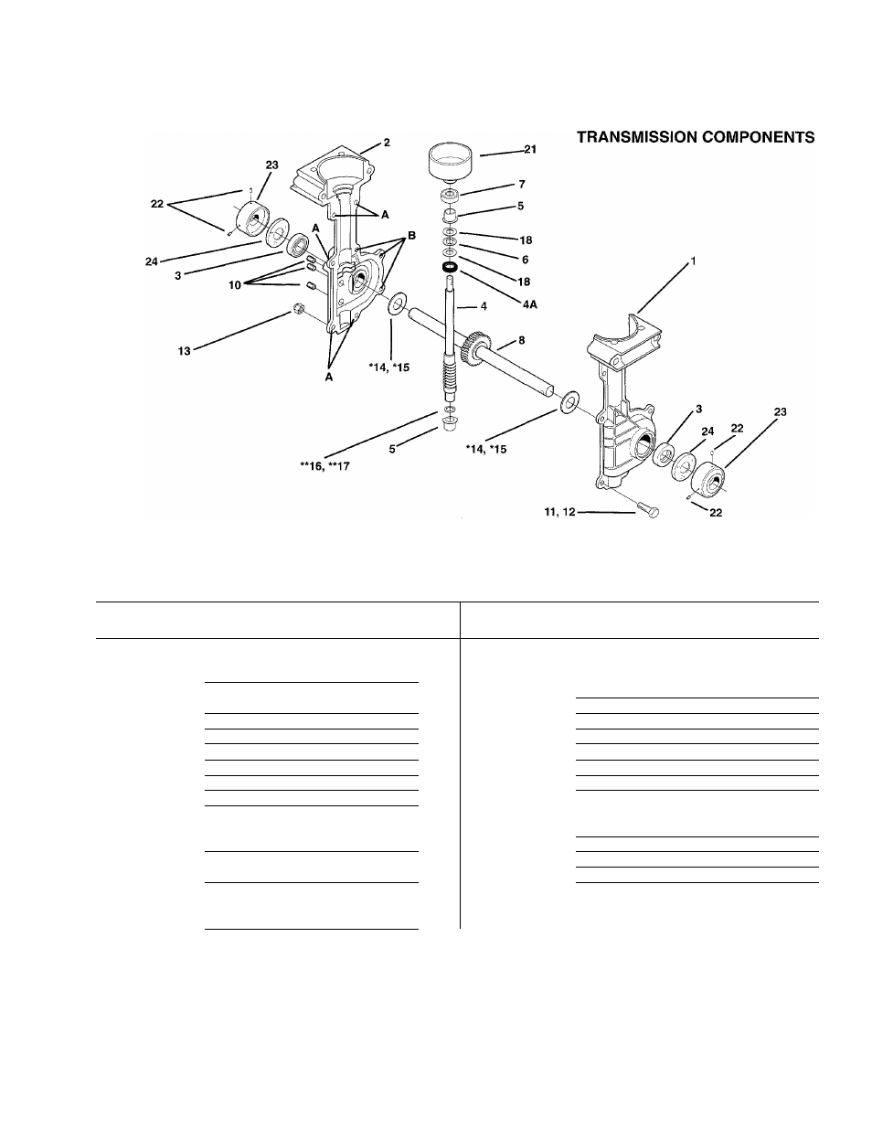
Replacement Parts - Figure 2
Replacement Parts - Figure 2
REF
No.
PART
No.
DESCRIPTION
QTY.
REF
No.
PART
No.
DESCRIPTION
QTY
1
1915039
Transmission Case, with pressed-
12
1100069
Screw, 1/4-20 x 1 (three
in bushing, ieft-side..................
1
locations identified as “B” on
2
1915040
Transmission Case, with pressed-
transmission case)................. .. 3
in bushing, right-side................
1
13
1817146
Locknut, Nyloc, 1/4-20............... .. 6
3
1983632
Oii Seai...................................
2
14*
1983635
Thrust Washer, output (.050)....... .. A/R
4
1983634
Shaft, worm-input......................
1
15*
1983640
Thrust Washer, output (.040)....... .. A/R
4A
1909923
Oii Seai, input............................
1
16** 1983641
Thrust Washer, input (.020)......... .. A/R
5
1983731
Bearing, input...........................
2
17** 1983642
Thrust Washer, input (.035)......... .. A/R
6
1983636
Bearing, thrust..........................
1
18
1983638
Thrust Washer......................... .. 2
7
1983637
Baii Bearing..............................
1
19
....
This Ref. No. Not Used
8
1904416
Shaft Assembly. Includes
20
This Ref. No. Not Used
pressed-on worm gear and two
21
1909486
Clutch Drum and Hub................ ..
1
ring lock pins.........................
1
22
1747166
Set Screw, 1/4-28x3/8................
.. 4
9
—
This Ref. No. Not Used
23
1915055
Dust Cover.............................
.. 2
10
1185741
Plug, 1/8.................................
3
24
1983713
Felt Washer...........................
.. 2
11
1111600
Screw, 1/4-20 x 7/8 (five locations
identified as “A” on transmission
case....................................
5
Used as required to reduce clearance and center the worm gear in the transmission case.
Used as required to reduce ciearance.
22