Assembly steps – Troy-Bilt 12157 User Manual
Page 10
Attention! The text in this document has been recognized automatically. To view the original document, you can use the "Original mode".
ASSEMBLY STEPS
You’ll need the following tools:
® Two 7/16" wrenches ( a 7/16" socket with a socket
extension and ratchet can be substituted for one of
the 7/16" wrenches).
* One medium size Philiips head screwdriver.
1. Unwind the throttle cable from around the en
gine. Do not kink or severely bend the cable.
2. Place the engine/transmission assembly so it
is resting on its “face” (the product name logo
label is face down).
3. Position the round end of the lower left han
dlebar in the slot on the left side of the transmis
sion - see Figure 3. (Look at the upper end of
the handlebar and check that the groove in the
half-round handlebar is facing inward. If not, in
stall the other lower handlebar in the slot.)
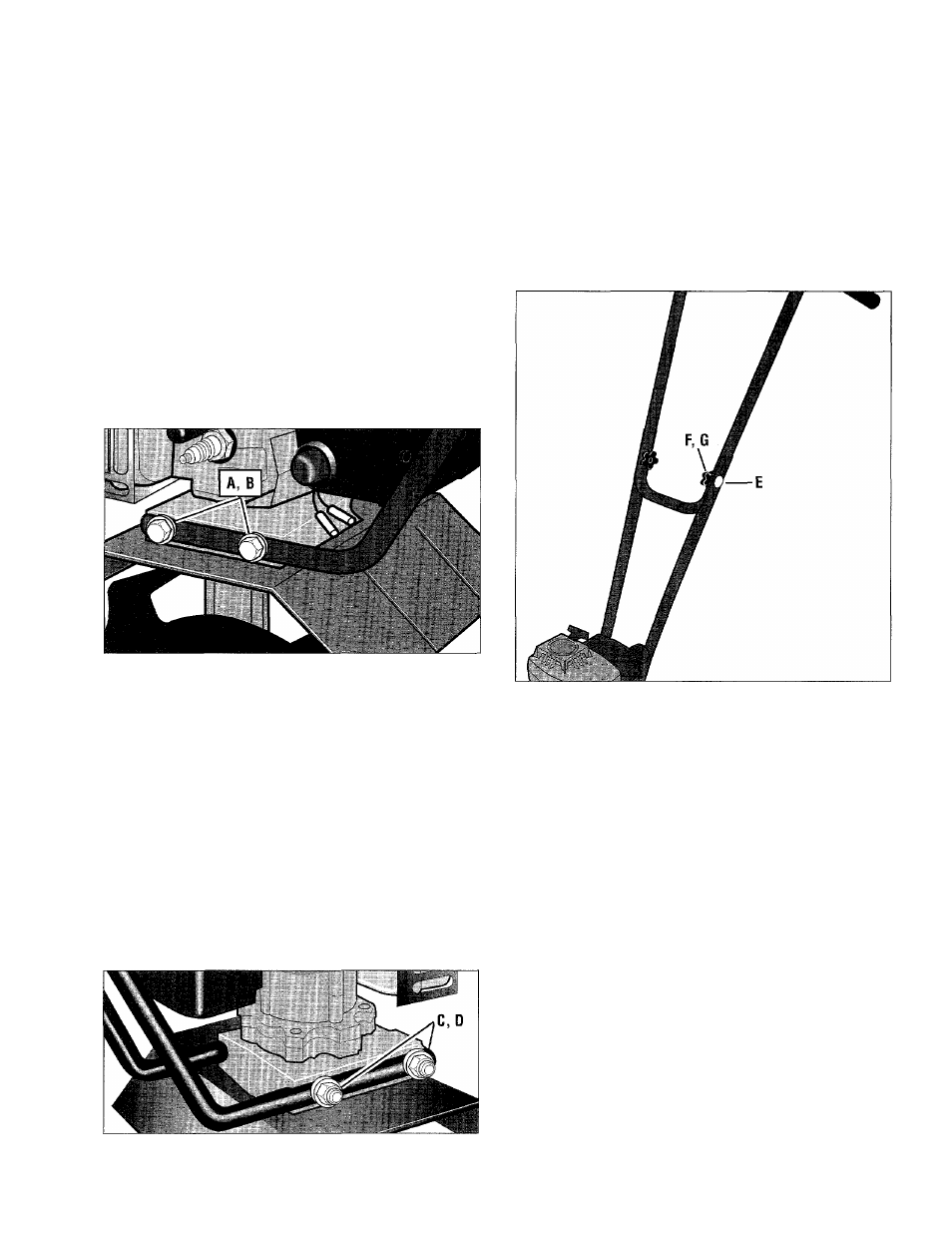
Figure 3: Attaching iower left handlebar.
4. Put a 1/4" flat washer (A, Figure 3) on the two
1/4"-20
X
5" long hex head screws (B) and insert
the screws through the handlebar and out
through the right side of the transmission.
5. Install the lower right handlebar over the ends
of the screws - see Figure 4. Install a 1/4" flat
washer (C) and locknut (D) on each screw.
6. Slowly and evenly tighten the two screws and
locknuts. Snug the nuts down, but do not over
tighten them.
7. Place the upper handlebar between the top
ends of the lower handlebars (rubber handlebar
grips face to rear).
8
. Align the hole in the left upper handlebar with
one of the two rectangular holes in the left lower
handlebar (the rectangular holes allow the han
dlebar to be adjusted higher or lower). From the
outside, insert a 5/16"-18 x 2" long curved head
carriage bolt (E, Figure 5) through the holes.
9. Put a 5/16" flat washer (F) on the bolt and
loosely thread on a handlebar knob (G). See
Figure 5.
10. Repeat steps 8 and 9 for the right side.
11. Tighten both handlebar knobs.
Figure 5: Attach upper handlebar to lower
handlebars (viewed from front of engine).
12.
Insert the #10-16 x 1-1/2" long pan head
Phillips screw (H, Figure 6) down through the
hole in the engine ignition On/Off Switch bracket
(I). Next, insert the screw through the hole in
front of the right side handlebar grip. Note that
the switch, wires and bracket are positioned to
the inside edge of the handlebar.
13.
Install the rectangular rubber spacer (J,
Figure 6) on the screw and turn the spacer so
that its long end points toward the grip.
14. Align the hole in the engine throttle lever as
sembly (K) with the end of the screw.
15. Hold the throttle lever assembly in place and
use a Phillips head screwdriver to firmly tighten
the screw.
Figure 4: Install lower right handlebar.
10