SINGER WRotary (Book 13) User Manual
Page 14
Attention! The text in this document has been recognized automatically. To view the original document, you can use the "Original mode".
A t t a c i l i f c i j«?de Fastener
Remove the regular press«- foot and attach ilu- Combination
Attaclimeiit in its place. Loosen
the
tliimib screw on the attach
ment and move the foot to the right or left: as desired. See that
the n«dle goes down in center of the needle hole before
tiglatemng the tliiimb screw.
IJ:ie needle holes on either side are cut deep enouali to allow
siiB.aeiit space between the metal of the slide fastener and the
line rfstitclimg so the fabric will not catch !n ii» slide pull as if
IS being opened and closed.
Fig. 23
higure^ca allows a slide fastener being stitched in a garment
With
the CoiTibination Adjustable Zipper Attaching and Cording
root positioned to the right of the needle.
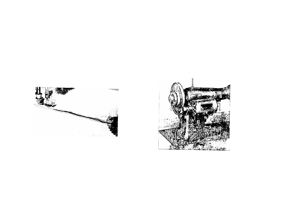
ELECTRICAL EQUIPMENT
Connections
Be sure that the motor pullev ], (Fig. 24) is so adjusted that: it
ceiiters^ on Ihe
jiand
wlieel for proper drhx; next,
see
that the
imsulatiiig^
bushnig (
2
) Ì
ouik
I
on the cord leading from the I'heostat
on
the inside ol tlie cabinet
is
properly placed in tlie hole found
in
ihe corner of the bed of the inacliine
(see
illiistratirm); ne:xt,
‘■ rrinetd the ttiree-contact connector plug
(
3
)
to motor terminal (’4 )
as shown in Ulustraiion: ne.xt. unwind the long wall plug
cord
from the storage reel and connect it to argv electrical oiilleì.
Fig. 24
un»
Lubi im
„1 mfoubacfoioii pomm, .me c* eaZh cm) Um motor shaft. 5
2 '
hu laotur liibiu uion. i'Lue one drop of oil
maily. depeiidiiig .ipon tin u-., ,
the
machine, or
evtic St., inouiiis.
I ig .'' pro
I 1 <'.acli occaspUiialU
n I'lositnatcd