SINGER W117 User Manual
Page 17
Attention! The text in this document has been recognized automatically. To view the original document, you can use the "Original mode".
Attaching a SUde Fastener
.
Fifure 28
Remove the regular presser foot and attach the Com*
bination Attachment in its place. Loosen the thumb screw
on the attachment and move the foot to the right or left as
desired. See that the needle goes down in center of the
needle hole before tightening the thumb screw.
The needle holes on either side are cut deep enough to
allow sufficient space between the metal of tiie slide fastener
and the line of stitching so the fabric wiU not catch in the
slide pull as it is being opened and closed.
Fig. 28 shows a slide fastener being stitched in a gar
ment with the Combination Adjustable Zipper Attaching and
Cording Foot positioned to the right of the needle.
To InstaU Sewing Machine Head on Cabinet
Thirty
°f-jt\ead binge
and
2)
‘“®.\ound s h a n k s
°Tthl
t w o h i n g e s
to back of
attached to^ of cab-
■'"It Tip head back
tighten
h e a d
s e t s c r e w s
(Fig® 2) securely.
^to^iS'ariea?
r°the motor as pos-
a?d slip motor
cord into
slot at
edge
f bed
p l a t e
and
nush
bushing
back
fnto hole in bed p|a
j
^
(see Fig. 9); y“ ^ord inside the cabinet, plug into an
wind the ef^f"®*and the machine is ready for operation,
base plug
' trehdle operated, merely place leather bel
“ Thind wheel drive pulley as of course there is no moto
^electrical connections.
_
.
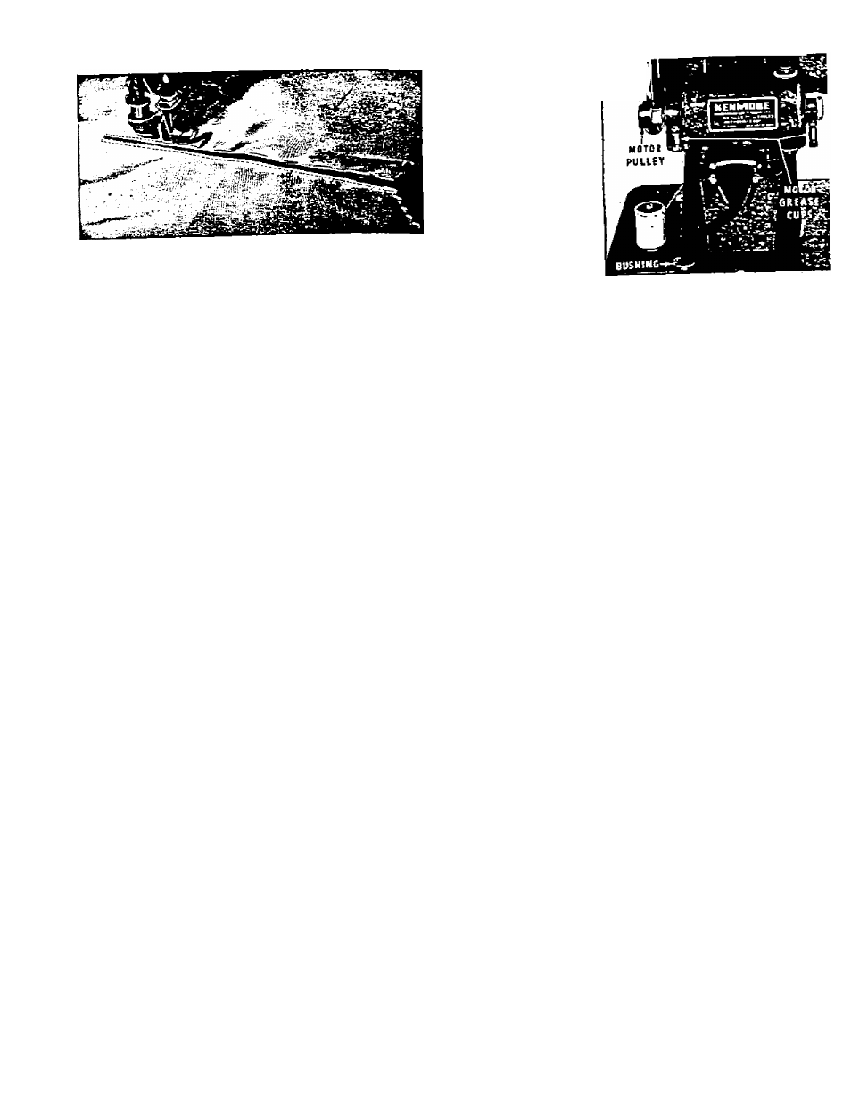
Motor Lubrication
/rtTic at either end of the motor shaft) provid
Two ““Purgation. Unscrew the caps and fill with petro
occasionally, depending upon the use of the ma
chine ^Sproximateiy every six months.
’
Speed Control and Current
„.v .loeired sewing speed is obtained by pressing th^
The
pressure from the knee lever auto
knee lever. Rem g
^e used on eithe
Tr or
DC,
no on IIB volts up to 75 cycles.
^
Motor Pulley
Ra sure the motor pulley (Fig. 9) is adjusted so i1
centers on the disc wheel of the machine.
Thirty-one