Section 3 step by step guides to install, Fig. 4, Fig. 5 – Sears 625.34823 User Manual
Page 9
Attention! The text in this document has been recognized automatically. To view the original document, you can use the "Original mode".
SECTION 3 STEP BY STEP GUIDES TO INSTALL
^ Close the shut-off valve on the house main wat©r
^ ‘ ‘ pipe, near the water meter or pressure tank, to
turn off the water.
^ Shut off the gas or electric supply to the water
*
heater.
Open the highest and lowest water faucets in
your house to let water drain from the pipes.
Close faucets after water has drained.
à
3.
Shutoff
Valve
Gas
Valve
Water
Meter
kl
TUj
¡j|
Electrical
j Panel
^ Take all the small parts from the parts bag and
lay out neatly where you can easily see and get
to them as they are needed.
NOTE: The inlet screen is not used on the clarifying
filter, and can be discarded.
FIG. 4
1 INLET
^SCREEN
GROUND
CLAMP (2)
dd
SMALL PARTS BAG ITEMS
INLET-OUTLET
ADAPTOR (2)
WASHER OR
GASKET (2)
n
INLET-OUTLET
TUBE (2)
UNLETOUTLET
'
NUT (2)
^ 0
GROUNDWIRE.
SCREWS AND NUTS
CLIP (2)
TRANSFORMER
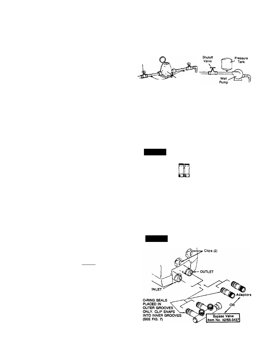
C INSTALL INLET AND OUTLET ADAPTORS OR
SEARS BYPASS VALVE, ITEM NO. 42/65-3437.
NOTE; If you ^ install the bypass valve, the adap
tors are not used. If you do not install the bypass
valve, you must use the adaptors.
FIG. 5
a.
INLET AND OUTLET ADAPTORS (Adaptors
and clips are small parts bag items.) - Push the
adaptors into the valve inlet and outlet ports
(FIG. 5 and 7) as far as they wilt go. Both adap
tors are the same and fit either valve port. SNAP
THE 2 LARGE HOLDING CLIPS INTO PLACE,
FROM THE TOP DOWN AS SHOWN. BE SURE
THEY SNAP FIRMLY INTO PLACE, SO THE
ADAPTORS WILL NOT PULL OUT. . .GO TO
STEP 6.
INSTALLING INLET AND OUTLET
ADAPTORS OR BYPASS VALVE