Sears 625.34823 User Manual
Page 10
Attention! The text in this document has been recognized automatically. To view the original document, you can use the "Original mode".
SECTION 3 STEP BY STEP GUIDES TO INSTALL
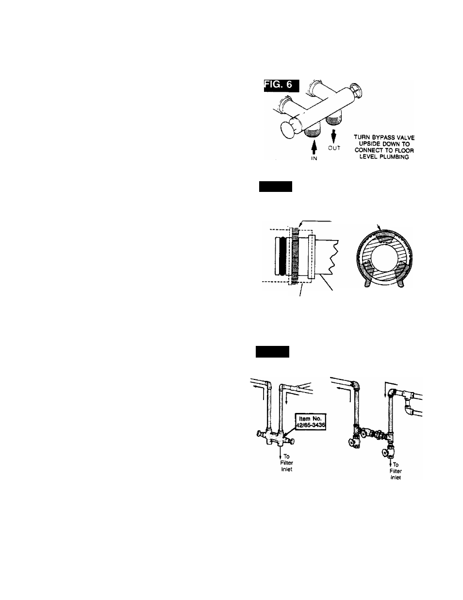
. BYPASS VALVE ITEM NO. 42/65-3437 - If not
D ■ already done, put a light coating of silicone grease
or Vaseline on the bypass vaive o-rings.
Push the bypass valve into the filter valve as far as
it will go (FIG. 5. 6 and 7). SNAP THE 2 LARGE
HOLDING CLIPS INTO PLACE, FROM THE TOP
DOWN AS SHOWN. BE SURE THEY SNAP FIRMLY
IN PLACE, SO THE BYPASS VALVE WILL NOT
PULL OUT. GO TO STEP 7.
FIG. 7
SIDE VIEW
END VIEW
CLIP-
Valve Body
Inlet or Outlet
Installation Adaptor
or
Bypass Valve
(Push all the way in)
6 INSTALLING 3 VALVE BYPASS, OR SEARS
■ BYPASS VALVE, ITEM NO. 42/65-3436, AND
PIPES (FIG. 8).
Cut the house main water pipe where you will
a, connect the filter. Loosely put together pipe, fit
tings, and the 3 valves or Sears special bypass
valve. Place valve(s) within easy reach.
IMPORTANT: WHEN LOOKING ATTHE FRONT OF
THE FILTER, THE INLET IS ON THE RIGHT SIDE.
IF WATER IN YOUR HOUSE MAIN WATER PIPE
RUNS FROM LEFT TO RIGHT, BE SURE TO USE A
“CROSS-OVER" AS SHOWN IN FIG. 2 AND 3,
PAGE 8.
FIG. 8
INSTALLING BYPASS VALVE
ITEM NO. 42/65-3436, OR
3-VALVE BYPASS
SINGLE VALVE BYPASS
3-VALVE BYPASS
If all pipe, fittings and valves fit together good,
tighten all threaded joints (use pipe dope on
outside threads), or solder all joints following the
soldering tips on page 20.
10