To install the upper handle and crank assembly, Assembly – Sears Craftsman 536.886531 User Manual
Page 8
Attention! The text in this document has been recognized automatically. To view the original document, you can use the "Original mode".
ASSEMBLY
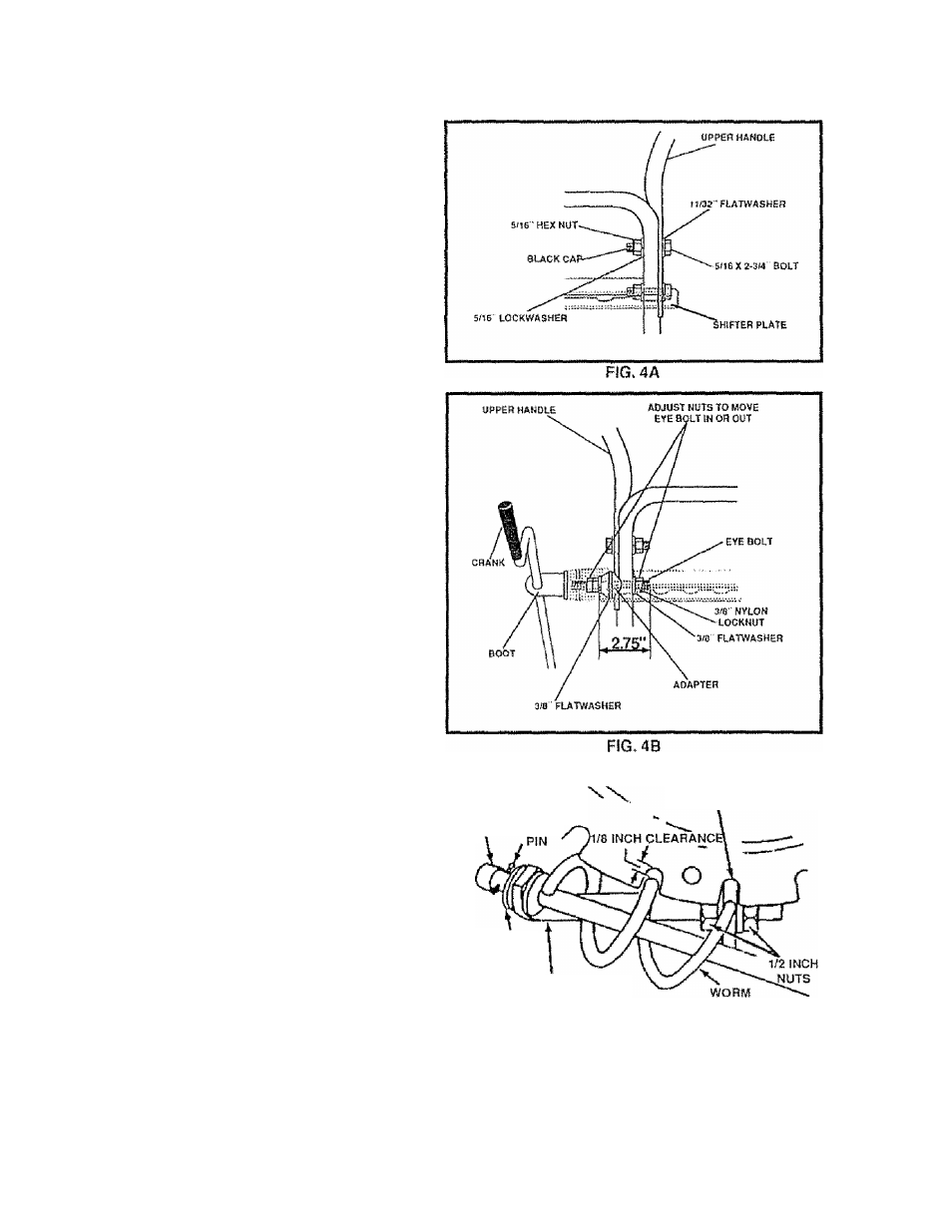
TO INSTALL THE UPPER HANDLE
AND CRANK ASSEMBLY
e
Remove
the
screws,
flaiwashers,
lockwashers,
and
hex nuts securing the shifter piate in the lower holes
of the lower handle and move shift lever to 3rd gear
® Loosen, but do not remove, the screws, flatwashers,
lockwashers, and hex nuts in the upper holes ol the
lower handle
® Raise upper handle into operating position. Upper
handle should be to the outside of the lower handle
and shifter plate to the inside
® Replace the right hand screw, tiatwasher, lockwasher,
and hex nut through the handle and shifter plate Do
not tighten until all boils are in place
NOTE: Unless you have the assistance ol another per
son, it may be easier to install one side of the handle at a
time.
® Remove the 3/8" nylon locknut and flatwasher from
the eye boll assembly (on the chute crank assembly
earlier) Check to make sure the two 3/8" jam nuts are
tight. The jam nuts should be 2 75 inches from the end
of the eye bolt (See Fig. 4B)
® Remove the plastic bag, the plastic cap, the cotter pin
and the washer from the
crank
assembly and set
aside (See Fig 5)
@ Rotate the notched section oi the discharge chute
toward the crank-adjusting rod (See Fig 5)
® install the wormed end of the crank through the hole
in the adjusting rod and secure the end with the
tiatwasher and colter pin, as shown in Fig 5
® Bend the ends of the cotter pin around the rod and
reinstall the plastic cap
® Install eye bolt through lower hole in the left hand side
of the handle and shifter plate (See Fig 4B)
® install the 3/8" flatwasher and the 3/8’’ nylon locknut
loosely on the ey bolt as shown in Fig 4B
® Tighten the eye bolt installed earlier, keeping eye in
line with the rod while tightening the inside securely
® Tightenthe screw, flatwasher, lockwasher and hex nut
at the lower right hand hole (See Fig 4A)
NOTE: Make sure the cables are no( caught between
the upper and lower handle
® Tighten two upper handle bolls
® Rotate the chute crank fully clockwise and lully counter
clockwise The discharge chulé should rotaie fully with
approximaiely
1/8
inch
clearance
beiween
the
worm
and the bottom ol the notch (See Fig 5)
PLASTIC \
CAP COTTER
NOTCHED SECTION
FLATWASHER
CRANK ADJUSTING ROD
FIG. 5
® If the chute crank needs to be adjusted, go to the
Service and Adjustments section on page 17 Screws
securing chute clips a! the base of the chute should be
slightly loose for easy rotation
NOTE: Be sure the crank does not touch the side of the
engine or the cover will be scratched.