Sears 486.244062 User Manual
Page 8
Attention! The text in this document has been recognized automatically. To view the original document, you can use the "Original mode".
18.
Raise hood and remove 3/8” carriage bolt and
nut from right hand side of frame. See figure 18.
LIFT _
LEVER
PLUNGER
REMOVE FRONT
CARRIAGE BOLT
AND NUT
FRONT —
RIGHT SIDE VIEW
FIGURE 18
19. Assemble support bracket onto right hand side
of
tractor
frame
(where
carriage
bolt
was
removed in step 15) using 3/8” x 1” carriage
bolt inside of frame and secure with 3/8” lock
washer and 3/8” hex nut, on outside of frame.
See figure 19.
ATTACHMENT
LIFT LEVER
LIFT LEVER
PLUNGER
FRONT-
BLADE PIVOT
1/4” HEX LOCK ROD
BLADE
3/8*^x
CARRIAGE
EYE BOLT
BOLT
3/8” LOCK /
WASHER 3/8” HEX NUT
RIGHT SIDE VIEW
HAIRPIN
COTTER
FIGURE 19
20.
Assemble the 1/4” eye bolt at the top of the
support bracket and secure with one 1/4” hex
lock nut. See figure 19.
21.
Assemble blade pivot rod through 1/4” eye
bolt as shown in figure 19. Secure lower end
of blade pivot rod through hole on right hand
side
of
blade
assembly
with
small
hairpin
cotter. See figure 19.
22.
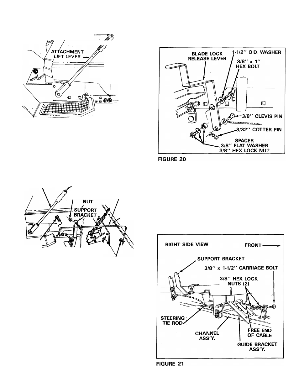
Assemble blade lock release lever to right side
of tractor frame using one 1-1/2” O.D washer,
one 3/8” X 1” hex bolt, spacer, 3/8” flat washer
and secure tightly with one 3/8” hex lock nut.
See figure 20.
23.
Secure one end of blade lock release cable to
small hole in blade lock release lever using one
3/8” X 3/4” clevis pin and one 3 /32” hairpin
cotter. See figure 20.
24.
Thread cable toward front of tractor under
steering tie rod and front axle and above guide
bracket assembly. See figure 21.
25.
Assemble one 3/8” x 1-1/2” carriage bolt into
top hole in angle lock bars and tighten secure
ly with one 3/8” hex lock nut. Place free end
of cable over threaded end of carriage bolt and
retain loosely with 3/8” hex lock nut. See figure
21
.