Lift – Sears 486.244062 User Manual
Page 6
Attention! The text in this document has been recognized automatically. To view the original document, you can use the "Original mode".
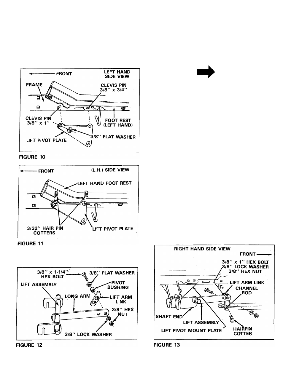
Assemble one lift pivot plate under left hand foot
rest and outside of frame. Secure front of lift
pivot plate with one 3/8" x 1" clevis pin, 3/8"
flat washer and 3/32" (small) hairpin cotter.
Secure rear of lift pivot plate with one 3/8" x
3/4" clevis pin and one 3/32" (small) hairpin
cotter. DO NOT ASSEMBLE
LIFT
PIVOT PLATE
UNDER THE RIGHT HAND FOOT REST AT THIS
TIME.
8. Pre-assemble lift arm link to inside of long arm
on lift assembly. As shown in figure 12.
9.
Assemble one 3/8" x 1-1/4" hex bolt through
3/8"
flat
washer,
through
pivot
bushing,
through large hole in lift arm link near angle end
and through hole in long arm nearest the end.
Secure with one 3/8" lock washer and one 3/8"
hex nut. See figure 12. NOTE: Lift arm link must
pivot freely.
NOTE
Lift arm link must be positioned as
shown in figures 12 and 13.
10.
Assemble one 3/8" x 1" hex bolt through
second hole from end of long arm. Secure with
one 3/8" lock washer and one 3/8" hex nut.
This bolt is used as a limit stop for the lift arm
link. See figure 13.
11.
Move attachment lift lever all the way forward
and lock in position. See figure 20, page 9.
12.
Hook lift assembly arms over both link rods,
assemble lift arm link over channel rod and
secure with one 1/8" (large) hairpin cotter. See
figure 13.
13.
Assemble one hitch brace (end with the large
hole), one 1-1/4" OD spacer onto each end of
the lift assembly pivot shaft. See figure 14.
14.
Insert pivot shaft end (from R.H. side of tractor)
into hole in L.H. lift pivot mount plate. See figure
14.