Sears 486.244062 User Manual
Page 7
Attention! The text in this document has been recognized automatically. To view the original document, you can use the "Original mode".
15.
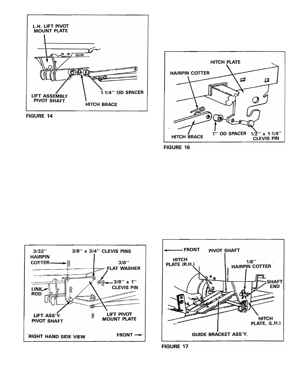
Assemble the other lift pivot plate, over right
hand end of lift assembly pivot shaft and
connect to outside of frame (see figure 15)
,
using
one
3/8” x 1” clevis pin from inside
through front hole in lift pivot plate. Secure with
3/8"
flat
washer
and
3/32"
(small)
hairpin
cotter. Secure rear of plate with one 3/8" x 3/4"
clevis pin and one 3/32" (small) hairpin cotter.
Secure ends of pivot shaft to each lift pivot plate
with 1/8" (large) hairpin cotter. See figures 14
and 15.
16.
Assemble the front end of each hitch brace
to the rear hole in each hitch plate using one
1/2" X 1-1/4" clevis pin, one 1" OD spacer and
one 1/8" hairpin cotter. See figure 16.
17.
Assemble guide bracket assembly shaft
end
into the left hand hitch plate. See figure 17. Slide
guide assembly back to the right and into hole
of the right hand hitch plate. Secure with a 1/8”
(large) hairpin cotter in each end. See figure 17.
Lower front end of guide bracket assembly to
straddle channel assembly.
FIGURE 15