To install the upper handle and crank assembly, Assembly – Sears 536.884811 User Manual
Page 8
Attention! The text in this document has been recognized automatically. To view the original document, you can use the "Original mode".
ASSEMBLY
TO INSTALL THE UPPER HANDLE AND
CRANK ASSEMBLY
•
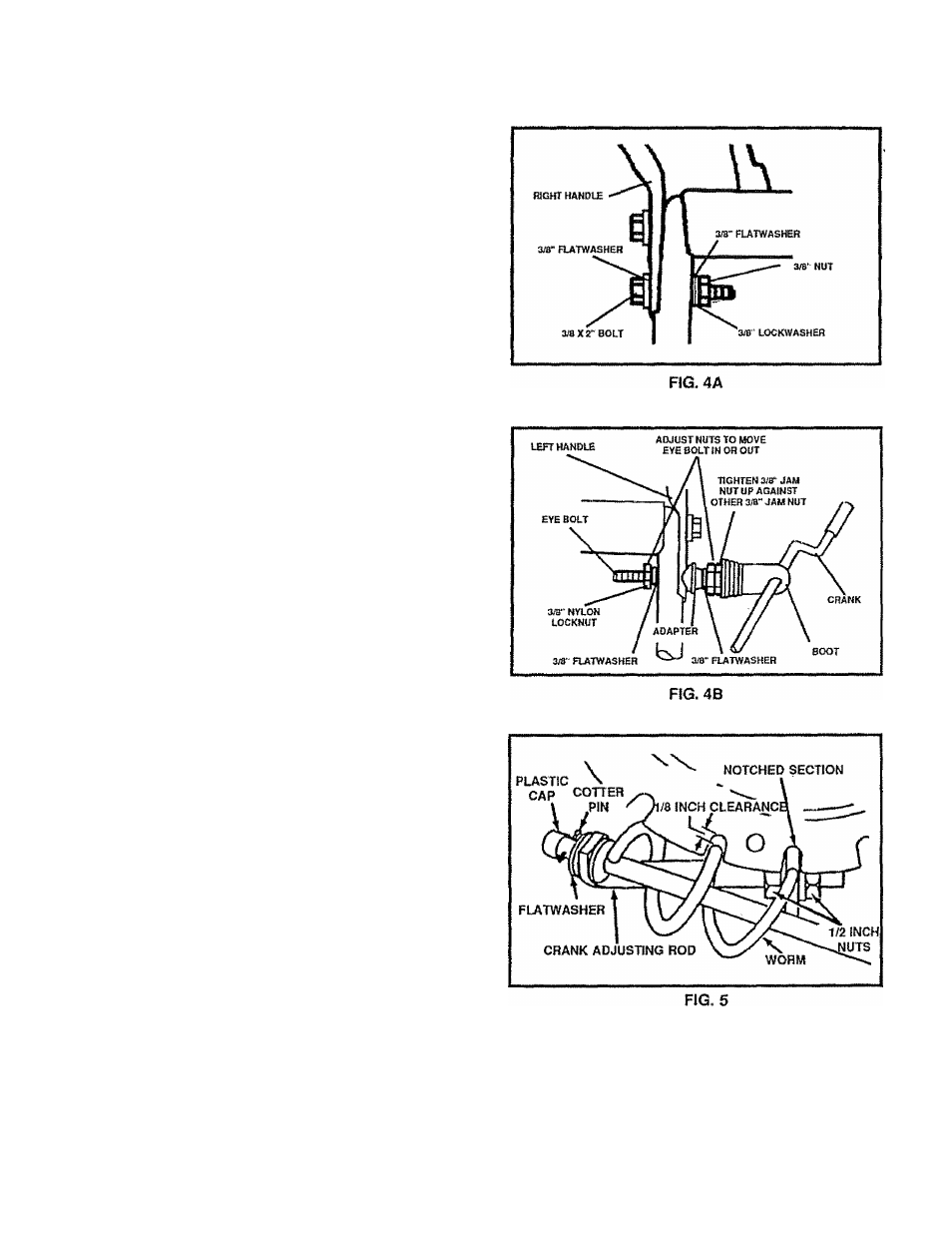
On the right side of the handle, install and secure the
following parts (found in parts bag) in the lower
handle hole as shown in figure 4A:
1 - 3/8"
X
2" boit
2 - 3/8" flat washers & 1 - 3/8" split lockwasher
1 - 3/8" nut
•
Remove the 3/8" nylon locknut and flatwasher from
the “eye" bolt assembly (on the chute crank assem
bly) and adjust the remaining 3/8" nut and flatwasher
on the "eye" bolt about half way up the thread.
Install “eye" bolt through lower hole on the left hand
side of the handle.
Install the 3/8" flatwasher and the 3/8" nylon locknut
loosely on the “eye" bolt, as shown.
Remove the plasticcap, the cotter pin and the washer
from the wormed end of the crank assembly and set
aside (See Fig. 5).
Rotate the notched section of the discharge chute
toward the crank-adjusting rod.
Install the wormed end of the crank through the hole
in the adjusting rod and secure the end with the flat
washer and cotter pin, as shown in Fig. 5.
Bend the ends of the cotter pin around the rod and re
install the plastic cap.
Tighten the eye bolt installed earlier, keep eye in fine
with the rod while tightening the inside nut securely .
Tighten the outside 3/8" jam nut up against the other
3/8" jam nut (See Fig 4B).
Rotate the chute crank fully clockwise and fully
counter-clockwise. The discharge chute should ro
tate fully to the outer diameter of the worm and shou Id
clear approximately 1/8" (see Fig. 5), If the chute
crank needs to be adjusted, go to the Service and Ad
justments section on page 17.
NOTE: Be sure the crank does not touch the side of the
engine or the cover will be scratched.