Install seat {see fig. 4), Check tire pressure, Check deck levelness – Sears 917.258524 User Manual
Page 8: Check for proper position of all belts, Check brake system, Assemble gauge wheels to mower deck (see fig. 5), Assembly, Seat
Attention! The text in this document has been recognized automatically. To view the original document, you can use the "Original mode".
ASSEMBLY
•
If this battery is put into service after month and year
indicated on label (label located between terminals)
charge battery for minimum of one hour at 6-10 amps.
•
First connect RED battery cable to positive (+) temiinal
with hex bolt, flat washer, lock washer and hex nut as
shown. Tighten securely.
•
Connect BLACK grounding cable to negative (-) termi
nal with remaining hex bolt, flat washer, lock washer
and hex nut. Tighten securely.
•
Close battery box door.
Open batte^ box door for;
•
Inspection for secure connections (to tighten hard
ware).
•
inspection for corrosion.
•
Testing battery,
•
Jumping (if required).
•
Periodic charging,
DISCARD TERMINAL
PROTECTIVE CAPS
uEv LOCK
WASHER
FLAT
WASHER
HEX
BOLT
POSITIVE
(RED) CABLE
NEGATIVE
(BLACK) CABLE
FIG. 2
SEAT
PAN
BATTERY
BOX DOOR
FIG.3
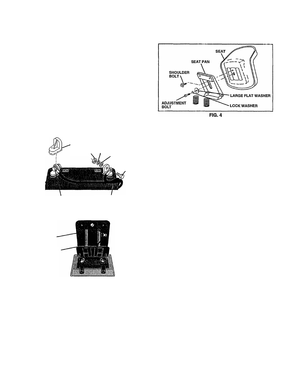
INSTALL SEAT {See Fig. 4)
Adjust seat before tightening adjustment bolt.
•
Remove cardboard packing on seat pan.
•
Place seat on seat pan and assemble shoulder bolt.
• Assemble adjustment boft, lock washer and flat washer
loosely. Do not tighten.
•
Tighten shoulder bolt securely.
•
Lower seat into operating position and sit on seat.
•
Slide seat until a comfortable position is reached which
allows you to press clutchjtirake pedal alt the way
down.
•
Get off seat without moving its adjusted position.
•
Raise seat and tighten adjustment bolt securely.
CHECK TIRE PRESSURE
The tires on your tractor were overinflated at the factory for
shipping purposes. Correct tire pressure is important for
best cutting performance.
•
Reduce tire pressure to PSI shown in "PRODUCT
SPECIFICATIONS" on page 3 of this manual.
CHECK DECK LEVELNESS
For best cutting results, mower housing should be properly
leveled. See TO LEVEL MOWER HOUSING" in the
Service and Adjustments section of this manual.
CHECK FOR PROPER POSITION OF ALL
BELTS
See the figures ttiat are shown for replacing motion and
mower blade drive belts in the Service and Adjustments
section of this manual. Verify that the belts are routed
correctly.
CHECK BRAKE SYSTEM
After you learn how to operate your tractor, check to see
that the brake is properly adjusted. See TO ADJUST
BRAKE” in the Service and Adjustments section of this
manual.
ASSEMBLE GAUGE WHEELS TO MOWER
DECK (See Fig. 5)
The gauge wheels are designed to keep the mowerdeck In
proper position when operating mower. Be sure they are
property adjusted to ensure optimum mower performance.
•
Adjust mower to desired cutting height (See TO AD
JUST MOWER CUTTING HEIGHT in the Operation
section of this manual).
•
With mower in desired height of cut position, gauge
wheels should be assembled so they are slightly off the
ground. Instatt gauge wheel in appropriate hole with
shoulder bolt, 3/8“ washer and 3/8-16 locknut and
tighten securely.
•
Repeat for opposite side installing gauge wheel in
same adjustment hole.
8