Operation, And operation – Sears 303.147012 User Manual
Page 8
Attention! The text in this document has been recognized automatically. To view the original document, you can use the "Original mode".
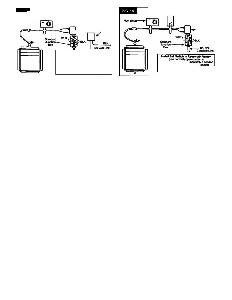
FIG. 17
WIRING INTO FURNACE
(For Fumaco with 120 VAC Singte Speed Blower Motor only)
•Humidistal
Furnace
Blower
Cmtrol
WHT.
Furnace
Blower
/\
Motor 120 VAC->-(
Single Speed V/
y
- -
WIRING TO CONSTANT 120 VAC UNE
EXTERNAL TO FURNACE
□ 6
Using low voltage wire supplied, connect spade ter
minals to solenoid valve on top of humidifier.
Q 7
Position and support wire to humidistat location.
Separate wire. Cut only one wire, strip ends.
O 8 Feed wires thru opening in humidistat back plate
and attach to screw terminals. Mount humidistat on return air ple
num using (4) #8 screws provided. Install shaft extension, cover
and knob (Fig. 16).
CONTROL CIRCUIT: For proper operation and water conserva
tion, this humidifier must be wired so it will operate only when the
furnace blower is running and the humidistat calls for additional
humidity. Two methods are shown (Fig. 17 and Fig. 18):
Fig 17: WIRING INTO FURNACE - FOR ANY FORCED AIR
FURNACE WITH SINGLE SPEED 120 VAC BLOWER ONLY.
CAUTION: Do not use this method with multi-speed blow
ers or blowers other than 120 VAC.
Fig 18: WIRING EXTERNAL TO FURNACE - FOR ANY FORCED
AIR FURNACE INCLUDING FURNACE WITH OTHER THAN 120
VAC BLOWER MOTOR OR FURNACE WITH MULTI-SPEED
BLOWER MOTOR.
NOTE: Some furnaces are equipped with accessory termi
nals that can be used for the humidifier. In this case, consult
the furnace manufacturer’s recommendation for wiring.
□ 9
_ Turn off electricity at fuse box. Using (two) wire nuts
and conduit nut supplied, install 24 VAC transformer to 120 VAC
supply junction box following the control oircuit selected so the
transformer will be powered only w^en the furnace blower is run
ning. Do not use existing transformer on furnace.
□
10
Connect spade terminals of low voltage wire to
spade terminals of treinsformer.
□
11
Turn on electricity and test operation by observing If
water is flowing to drain while furnace is running arid humidistat
dial is set to “tesT position.
Salt Switch
-24 VAC
Transformer
Purchase this accessory! _____
Available from Sears Product J
Phot»: 1-SOO-366-7278
Specify Division 42 PLS042 PI, No. 9114
NOTE: Wiring must conform to local codes.
□
12
Attach “Operating Instruction LabeT to return air ple
num next to the humidistat. Peel off paper backing and stick l£d>el
in desired location.
operation
□
1
Set knob to the lowest temperature predicted for a
24 hour period. Because of differences in house construction you
may want to tiy a higher or lower setting to adiieve proper humidity.
n 2
Change
knob
settings
as
outdoor
temperature
changes occur.
WARNING: DO NOT LEAVE KNOB SET IN “TEST POSI
TION ABOVE “+20" OR HUMIDIFIER WILL RUN CON
STANTLY.
IF SWEATING OF WINDOWS OR WALLS OCCURS OR IF AIR
IS TOO DRY:
Check dial setting. Indicator should point to the lowest 24 hour
temperature. If setting does not agree, readjust knob to proper
number and wait 24 hours for sweating to stop. If dial setting was
correct and conditions have not changed, rotate knob back and
forth from TEST to MINIMUM HUMIDITY SETTING. If humidifier
goes ON and OFF, control is operating properiy.
AIR CONDITIONING - IMPORTANT:
If your furnace has air conditioning (cooling), close the damper
completely during summer months and turn the humidistat to the
Minimum Humidity setting. BE SURE TO OPEN DAMPER DUR
ING HEATING SEASON AND RESETTHE HUMIDISTAT.
WATER FLOW RATE:
At standard water line pressure of 50-60 PSI (pounds per squEkre
inch), water will flow through humidifier at approximately four (4)
gallons per hour. About 0.7 gallons per hour of the four wilt be
evaporated, leaving 3.3 gallons to be drained away. Since the fur
nace only runs an estimated 30-40% of the heating season, and
the-humidifter is wired to operate only with №e furnace blower,
and only when humidity is required, the actual amount of water
drained per day is much less than would be expected.