Installation, Ch 1, Cj 2 – Sears 303.147012 User Manual
Page 6: Lj 3, Ch 5
Attention! The text in this document has been recognized automatically. To view the original document, you can use the "Original mode".
□
11
Attach collar and flexible hose to cold air plenum us
ing (5) #8 screws provided. If additional flexible hose is required an
eight foot length is available through the parts department order
28115205. Before tightening screws insert damper between coliar
and plenum (Fig. 10). It should be open for humidifier operation.
FIG. 10
Damper Blade
(Slide shut
before using air
conditioning.
Slide open at
start of heating
season.)
□
12
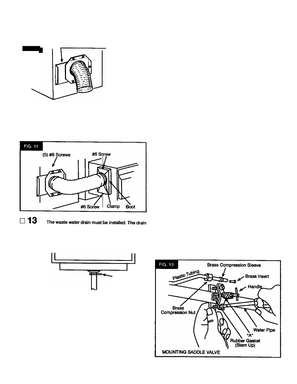
Attach boot to humidifier using (2) #6 screws en
gaged in the tinnerman nuts provided in bypass flange. Connect
№e flexible tube as shown using clamp provided. Do not allow
flexible tube to come within 3' of furnace flue pipe because of flue
pipe's extreme heat (Fig. 11).
is in the bottom of the humidifier reservoir (Fig. 12). Use M2" I. D.
X icr plastic tubing to connect drain. (Tubing is supplied.) Addi
tional tubing is available at your Sears store, Stock No. 42-3433
Spring
Hose
Clamp
K Hose To
Drain
CAUTION: Wear safety glasses.
□ 14
Using ^ng hose clamp pliers, expand hose damp
and slide over end of plastic tubing approximately 2 inches. Slide
plastic tubing onto waste water drain. ExpowJ hose damp and
position to damp tubing to waste water drain (Fig. 12).
installation
WATER SUPPLY
CAUTION:
Use plastic tubing supplied. Do not use copper
tubing because It may become disconnected when used with
hardware supplied.
CH 1
Water for the humidifier must be taken ^om a nearby
cold water line. Turn off the water supply. Drain by opening a fau
cet at a lower level of the line.
CJ 2
Mount the saddle valve on the water line as close to
the humidifier as possible. You have been supplied with (10) feet
of 1/4' plastic tubing.
SPECIAL NOTE: When measuring the distance from the
saddle valve location to the humidifier, keep in mind that the
tubing must be supported; therefore, it must mn along cdling
and walls. Measure along the path the tubing will foilow.
LJ 3
Back out the piercing pin by turning the T* handle
counter dockwise and then damp the saddle valve body securely
on the water line vwth rubber gasket positioned as shown (Rg. 13).
On gaivanized or copper pipe over 5/8', first drill a 5/32' hole.
CAUTION: For safety use a hand drill or grounded electric
drill.
C! 4 Turn handle clockwise untii it has pierced the water
line and valve is completely closed (Fig. 13).
CH 5
Partially uncoil the tubing. Slide the brass compres
sion nut over the tubing. The threads in the nut must face the
tubing end. Place the brass compression sleeve as shovwi (Fig.
13). Slip brass insert into end of tubing.
Q 6 Insert the tubing end into the saddle valve at
threaded stem “A" (Fig. 13) as far as it will go. Thread the brass
compression nut onto the valve, then tighten gently with a wrench.
Take care not to overtighten the nut.