Sears 625.34929 User Manual
Page 8
Attention! The text in this document has been recognized automatically. To view the original document, you can use the "Original mode".
-- s
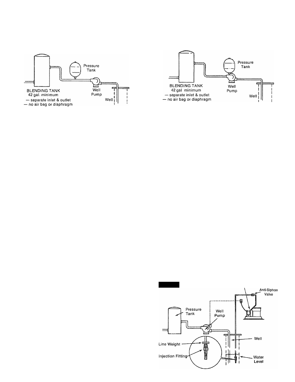
PRESSURE TANK INSTALLED “ON" THE MAIN
SUPPLY LINE
CAPTIVE AIR PRESSURE TANK INSTALLED "ON"
DISCHARGE SIDE OF WATER PUMP
GUIDES TO INSTALL YOUR SO:.lT':;;i-i ;::L=L'[';i-:-:-5LVT .iYSy-V;
® SOLUTION INJECTION INTO THE WELL CASING
1. Set the solution dispensing system in the piece
you chose to locate it. See page 7 for guides.
2. Measure for the length of tubing needed to run
from the solution pump discharge fitting down to
the water level in the weil. The tubing is stiff, so
allow enough length for longer bends. Cut both
ends of the tubing square with a sharp knife.
NOTE; The system includes 15 ft. of tubing. If more
is needed, look at the parts list on page 19. You can
use a bulkhead fitting (Key #5, page 19} to join
tubing together.
3. Remove the nut from the discharge valve (FIG.
4) on the solution pump. Slide the nut over 1 end of
the tubing. Push the tubing onto the tip of the
discharge valve as far as it will go. Then slide the
holding nut onto thevalve and tighten it with your
fingers.
NOTE: To prevent siphoning of solution, buy (see
page 19) and install an anti-siphon valve as shown
in FIG. 4. Siphoning of solution may occur when
the solution dispensing system is located above
the injection point fitting.
4. In the same way as in step 3, connect the other
end of the tubing to the injection fitting.
NOTE: Looking at FIG. 4, put some weight on the
tubing so the injection fitting will stay under water.
Large steel washers(3/8"i.D.)make good weights.
5. Lower the injection fitting down into the well.
CAUTION: In cold weather climates, you must
insulate this tubing so it will not freeze.
DO NOT REMOVE THE PLASTIC SLEEVE FROM
THE TIP OF THE INJECTION FITTING. (T IS A
WORKING PART.
SEE PAGE 11 TO MAKE THE NEEDED ELEC
TRICAL CONNECTIONS.
iiMWI
Pump Head
Discharge Fitting