Figure 4, Installation step 10, Install the safety reversing sensor – Sears CRAFTSMAN 139.53640SRT User Manual
Page 22: Figure 2, Figure 3, Figure 4 figure 5
Attention! The text in this document has been recognized automatically. To view the original document, you can use the "Original mode".
Installation Step 10
Install the Safety Reversing Sensor
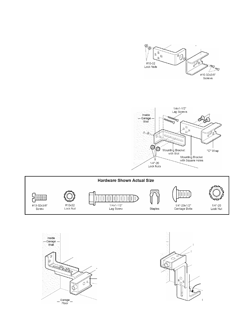
Figures 2 and 3 show assembly of brackets and
"C" wrap based on the recommended installation of
the sensors as shown on page 21.
However, Figures 4 and 5 are variations which may
fit your installation requirements better.
Make sure
the wraps and brackets are aligned so the
sensors will face each other across the garage
door.
• Fasten the "C" wraps to the mounting brackets
having square holes, using the hardware shown
in Figure 2,
• Connect each assembly to a slotted bracket, using
the hardware shown in Figure 3.
Note the alignment of the brackets for left and
right sides of the door.
• Finger tighten the lock nuts,
• Use bracket mounting holes as a template to
locate and drill (2) 3/16" diameter pilot holes on
both sides of the garage door, 4"-6" above the
floor
but not exceeding 6".
(See warning on
page 21.)
• Attach bracket assemblies with 1/4"x1-1/2" lag
screws as shown in Figure 3.
• Adjust right and left side bracket assemblies to the
same distance out from the mounting surface.
Make sure all door hardware obstructions are
cleared. Tighten the nuts securely.
Figure 2
Mounting Bracket
With Square Holes
C" Wrap
Figure 3
1/4-20x1/2" Carriage Bolts
(with square shoulder)
Figure 4
Figure 5
Alternate Wall Mount
Alternate Floor Mount
Mounting Bracket
with Slot
Mounting Bracket
with Square Holes
C" Wrap
Sensor
Indicator Light
inside
- Garage
•'.Wall..
"C" Wrap
ndicator Light
Sensor
Mounting Bracket
with Square Holes
^ Mounting Bracket
with Slot
Attach with
concrete anchors
(not provided)
22