How to set-up your chipper-shredder – Sears 770-7387F 247.78089 User Manual
Page 6
Attention! The text in this document has been recognized automatically. To view the original document, you can use the "Original mode".
Spacers
(Inside
Hinge
Lock
Washer and
Hex Nut
Hand
Knob
Hex Bolt
4" Long
Chute
Deflector
HOW TO SET-UP YOUR CHIPPER-SHREDDER
A
MAKE CERTAIN THE SPARK PLUG WIRE
IS DISCONNECTED AND MOVED AWAY
FROM THE SPARK PLUG BEFORE AS
SEMBLING THE CHIPPER-SHREDDER.
Upper
Guide
Assembly
FIGURE 3.
Hat Washer
Hex Lock Nut
ATTACHING THE CHUTE DEFLECTOR
• Place one flat washer 1/4" I.D., then one spacer 1/4"
I.D. on hex bolt 4" long.
• Place chute deflector in position on the discharge
opening, on the left side of the chipper-shredder.
• Insert hex bolt through hinge on chute deflector and
----- housing (spacer fits inside of hinge). See figure 2.
• Place the second spacer 1/4" I.D. over the hex bolt,
inside the other part of the hinge. Secure with 1/4"
I.D. flat washer, lock washer and hex nut. Tighten
securely.
• Secure both sides of chute deflector to housing us
ing hand knobs and cupped washers 5/16" I.D.
(cupped side of washers go against chute deflector).
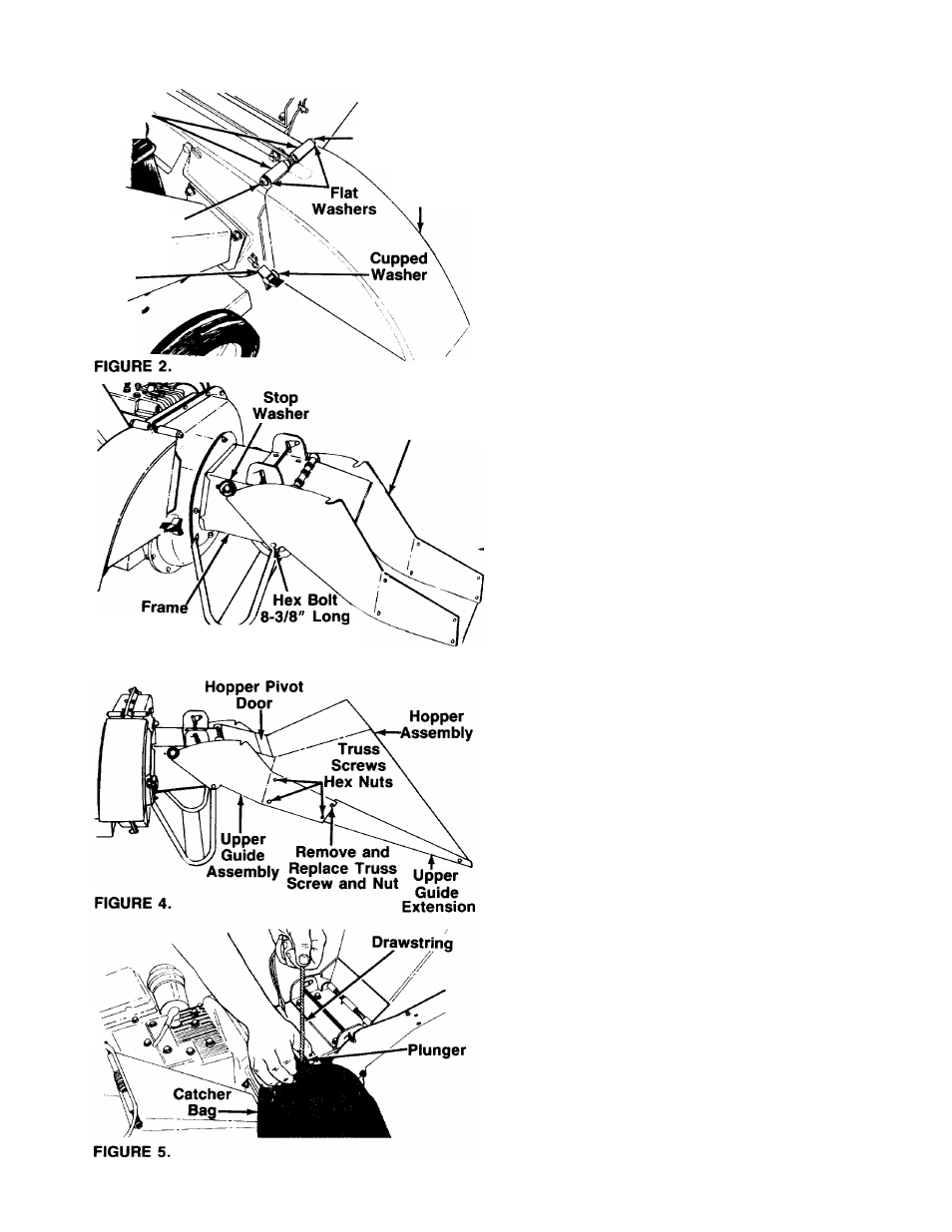
ATTACHING THE UPPER GUIDE ASSEMBLY
Insert hex bolt 8-3/8" long thru upper guide assembly
and frame. Secure with flat washer 5/16" I.D. and hex
lock nut. Make certain edges of the upper guide assem-
-bly are underneath stop washers. See figure 3. Plastic
insert in hex nut should face away from upper guide
assembly. Tighten hex nut until parts are snug, but so
upper guide assembly can still be rotated on the frame.
ATTACHING THE HOPPER ASSEMBLY
Your chipper-shredder has been shipped with the upper
guide extension attached to the hopper assembly. See
figure 4. Attach the hopper assembly to the upper guide
assembly as follows:
NOTE:
If desired, lift up on the release bar (see figure
6, inset) to raise the upper guide assembly so you can
attach the hopper assembly while standing instead of
kneeling.
• Remove one truss machine screw and nut from each
—side of hopper assembly. See figure 4. Push hop
per pivot door down inside lower part of hopper. The
hopper assembly fits inside upper guide assembly.
•
Secure hopper assembly using truss machine
screws and nuts just removed, and six additional
screws and nuts found in hardware pack. The heads
of truss machine screws should be to inside of hop
per guide assembly. Tighten all nuts finger tight. Lift
hopper assembly and snap into raised position.
Tighten all nuts securely.
ATTACHING THE CATCHER BAG
Your chipper-shredder is equipped with a catcher bag
to catch the shredded material.
-•To attach the bag, place the opening of the bag over
the chute deflector so it completely covers the chute
opening. Depress the plunger on the drawstring, pull
on the drawstring until the bag is tight around the
chute opening. Release plunger to lock it into posi
tion. See figure 5.