Specircatfon chart, Glossary, General information – Sears 150270 User Manual
Page 5: Description of operation
Attention! The text in this document has been recognized automatically. To view the original document, you can use the "Original mode".
SPECIRCATfON CHART
Mode! No.
919.150270
Horsepower
%
SCFM @ 40 psig
2.7
SCFM@90psig
го
C^sptacement CFM
4.0
Bore
2%"
Stroke
.r .
Vbifage-Single Phase
110-120
Minimum aanch Circuit Requirement
15 AMPS
“Fuse туре
Time Detey
Amperage at Max. Presafre
10.6
*A ciroilt brealier is pref©nw3. Use only a fuse or circuit breaker that is the saane rating
as
tt>e branch circuit the air
compressor is operated on. if the air compressor Is connected to a circuit protected by fuses, use time delay fuses.
GLOSSARY
SCf=M or CFM: Standard Cubic Feet per Minute; a unit
cS
mea^rement of air deiivery.
PSIG or PSI; Pounds per square inch gauge.
U,L Listed; Underwriter Nioratwies; samples of com
pressor outfits, taken from production,
submitted to
U.L and found to comply with their requlremente for
design and perfimnance.
GENERAL INFORMATION
Congratulations! >bu have purchased a one cytind^, %
HP compact oHtess compressor. The absence of a tank
gives y^u added mobility as well as ease in stcKaqe,
while the % HP mcdw ^lows
to utiliz® many air tools,
including inflate»®, blow guns, spray guns, air brushes,
caulking guns and etchers. Oiiless design means you
never have to add oil and its oiiless feature also guaran
tees that you will sf»^ay ^rely oil-free air.
A14* X15' air hose is supplied with your compr^or, as
virell as an air chuc^ Accessories for use with your new
compressor are available through the current Sears
sales cata!(^, or at full line Sears stores. Your compres
sor will operate many ac^sories. Check the pressure
and flow rating recommended
b/
the accessevy manu
facturer- be sure it is compatible wfii the delivery of
your compressor.
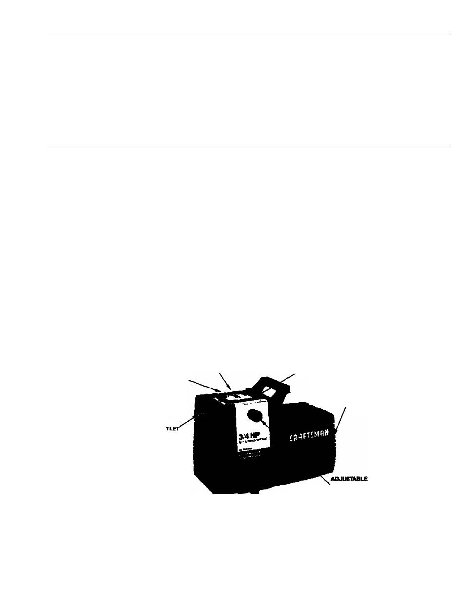
DESCRIPTION OF OPERATION
АЛГаГЮСЕ
fnot
к/юшп)
AIR
00
ADAPTER
AIR INTAKE
FILTER
(notriwm)
AIRCOMPfl^SOR
RIMP
AM COMPiffiSSOR
MOTOR
figurm 1
Air Compressor Pump; lb compress air, the piston
moves up and down in the ^linder. On the downstroke,
air is drawn in through the air intake muffler. The exhaust
valve remains closed. On the upstroke of the piston, air is
compressed. The intake valves close and compressed
air is forced out through the exhaust valve and then
through the air hose.
PRESSURE
VJU-VC
KNOB
Ad|usteble Pressure Valve Knob: The pressure valve
knob contiDls the amwint pressure going from the air
compressor to the acce^ory. Pressure can be set at any
point between 10 and 100 RS.l. (100 RS.i. is the highest
pressure tills compressor mil deliver.) Always set the
pressure valve knob at or below the required pressure for
the accessory being used. THE ADJUSTABLE PRES
SURE VALVE KNOB MUST BE SET AT “START"
BEFORE YOU START THE COMPRESSOR.