Compressor pump diagram i^rts list, Not illustrated – Sears 150270 User Manual
Page 11
Attention! The text in this document has been recognized automatically. To view the original document, you can use the "Original mode".
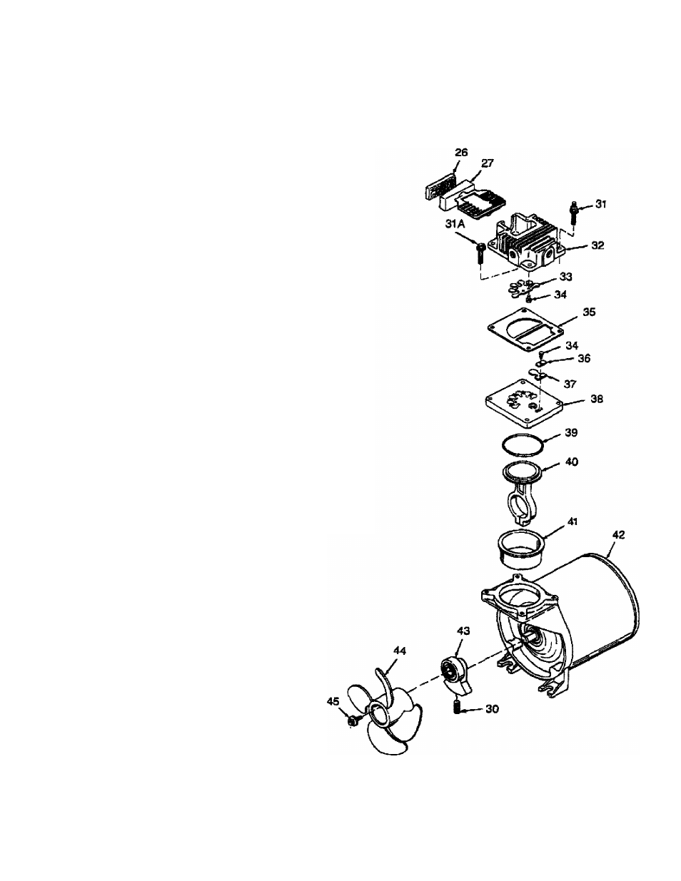
COMPRESSOR PUMP DIAGRAM
I^RTS LIST
KEY
NO.
R4RT NUMBER
DESCRIPTION
26
CAC-260-2
Filter
27
CAC-1018
Intake muffle
28
—
Not used
29
—
Not used
30
SSF-2Q43
Set screw
31
SSF-6637
Shoulder stud
V
a
"-W
x
1
Ve"
31A
SSF-927
(2 used)
Screw
Vt'-SOicV/a"
i^*^32
CAC-4234
(2 used)
Head assy.
33
CAC-245-1
tapper valve intake
34
SSF-9821
Sciew#5-40xVi*'
35
CAC-251-2
(3 used)
Gasket
36
CAC-369
RestrlettH’
37
CAC-246-3
Flapper valro exhaust
GAC-4203-1
№ve plate assy.
39
SSG-0133
O-ring
40
CAC-4202
Connecting rod assemMy
41
CAC-249-1
Cylinder sleeve
42
M0-6421
Motor y«HF
43
CAC-4201
Ect^ntrle assembly
m
44
CAC-255-1
Fan
45
SSF-3101
Screw #10-24 xy«"
NOT ILLUSTRATED
9-16163
9-16271
SI-30-08-2-C
Hose BSsemUy
(v*"
x 15)
Air chuck
Owners Manual
^ Key 44, can only be purehaasd
as part of KK-4465 which
includes (1) SSF-31Q1 (Key 45).
Key 40,41 can only be
purchased as part of
KK-4464
connecting
rod kit
Key 32, Includes 1 ea. of Key 33 &
34
4^ Key 38, includes 1 ea, of Key 34,36 & 37
n