Additional installation materials, The sump, Specifications – Sears 390.303491 User Manual
Page 3: Pump installation
Attention! The text in this document has been recognized automatically. To view the original document, you can use the "Original mode".
4.
This pump is recommended for use in permanent instal
lations only. Do not install on clay, earth, or sand surfaces.
A
CAUTION I
Pump must be level (column must be verti
cal) when operating. If motor is tilted, internal start/run
switch may overheat and damage motor.
ADDITIONAL INSTALLATION
MATERIALS
SumpAJtility Pump Hose Kit, SEARS Stock No. 27909, con
taining 24’ of 1-1/4” flexible plastic pipe, a 1-1/4” plastic
adapter and a stainless steel clamp.
Check Valve, SEARS Stock No. 2789 or 2792.
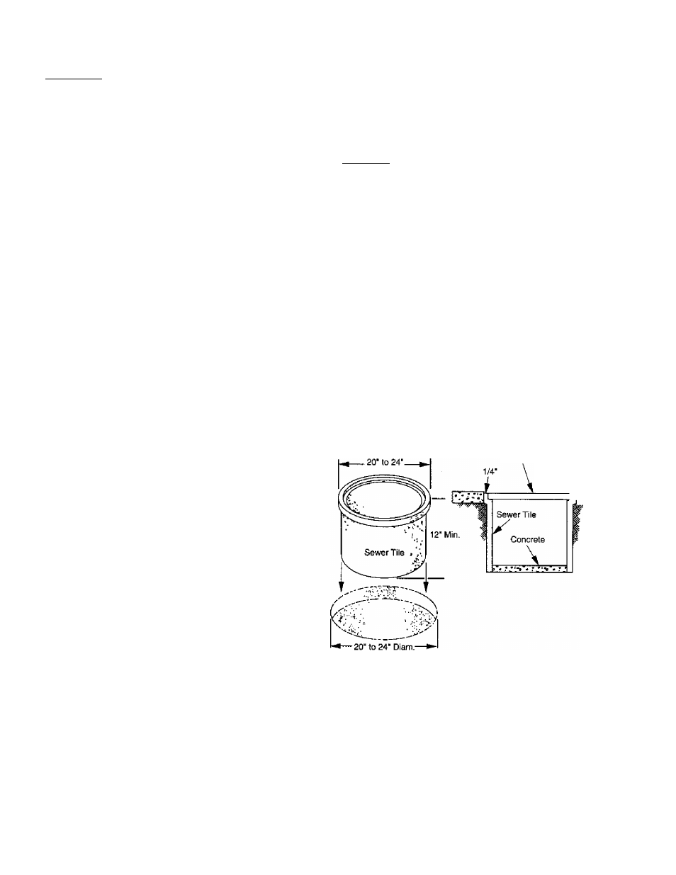
THE SUMP
The sump should be located at the lowest place in the base
ment or area to be drained. Floor drains from other areas in
the basement may be tiled into the sump. Drain tile aroimd
a house foundation can also be tiled into the sump, effec
tively removing water and relieving pressure from this area.
A suitable sump can be a 20" or 24" sewer tile. Sump must
be at least 12” in diameter.
A sump cover is desirable to exclude refuse from the sump.
Consult local code for sump cover specifications.
SPECIFICATIONS
Power supply required......................................... 115V, 60 HZ.
Horsepower (390.303302) .....................................................1/3
Horsepower (390.303491) .....................................................1/2
Motor duty..............................................................Intermittent
Uquid Temp. Range........................... 32° F to 70° F (0°-2TC)
Individual Branch Circuit
Requirement GFCI Class A.....................................................15 Amps
Motor full load (maximum - 390.303302)..............................3.5 Amps
Motor full load (maximum - 390.303491)..............................7.3 Amps
Dischai^e (390.303302)...................................................... 1-1/4" NPT
■»ischarge (390.303491)................................................... 1-1/2" NPT
PUMP INSTALLATION
Check your local Electrical and Plumbing Codes before in
stalling pump. You must comply with their rules.
Set the pump on the bottom of the sump, making sure that
it sits solidly and is level. Be sure there is enough space
around the pump to allow the switch free movement as
the sump water level changes. Do not install on clay,
earth, or sand.
A
CAUTION Rjsk
of flooding. If a flexible discharge
hose is used, pump may move around in sump
when motor starts. If it moves far enough so that the
switch hits the side of the sump, the switch may stick and
prevent pump from starting. Make sure that pump is se
cured so that it cannot “walk around” in sump.
NOTE: To avoid backflow into the sump when the pump
shuts off, install a Check Valve, SEARS Stock No. 2789, in the
threaded discharge port of pump (390.303302) or l-l/2”xl-
1/4” reducer bushing (390.303491). Reducer bushing is in
cluded with Model
3 9 0 .3 0 3 4 9 1. Be sure arrow on check
valve body points away from the pump. This Check Valve is
equipped with an air bleed hole to prevent airlocking the
pump. If using any other check valve, drill 1/8” (3,2 mm)
hole in discharge pipe just above pump body but below
check valve to prevent air locks.
Use 1-1/4” plastic pipe from Hose Kit No. 27909 for the dis
charge pipe. Run the dischaige pipe to the nearest sewer
outlet or other point of disposal. Use the most direct route
with the fewest turns and elbows possible.
Use Teflon tape to seal threads in plastic pipe. Hand tighten
only.
Sump Cov
0
r
Basement Floor
S
5
Figure I