Assembly instructions, Lubrication, Assembly instructions belt adjustment – Homelite 24666 User Manual
Page 3
Attention! The text in this document has been recognized automatically. To view the original document, you can use the "Original mode".
ASSEMBLY INSTRUCTIONS
BELT ADJUSTMENT
fe(
1.
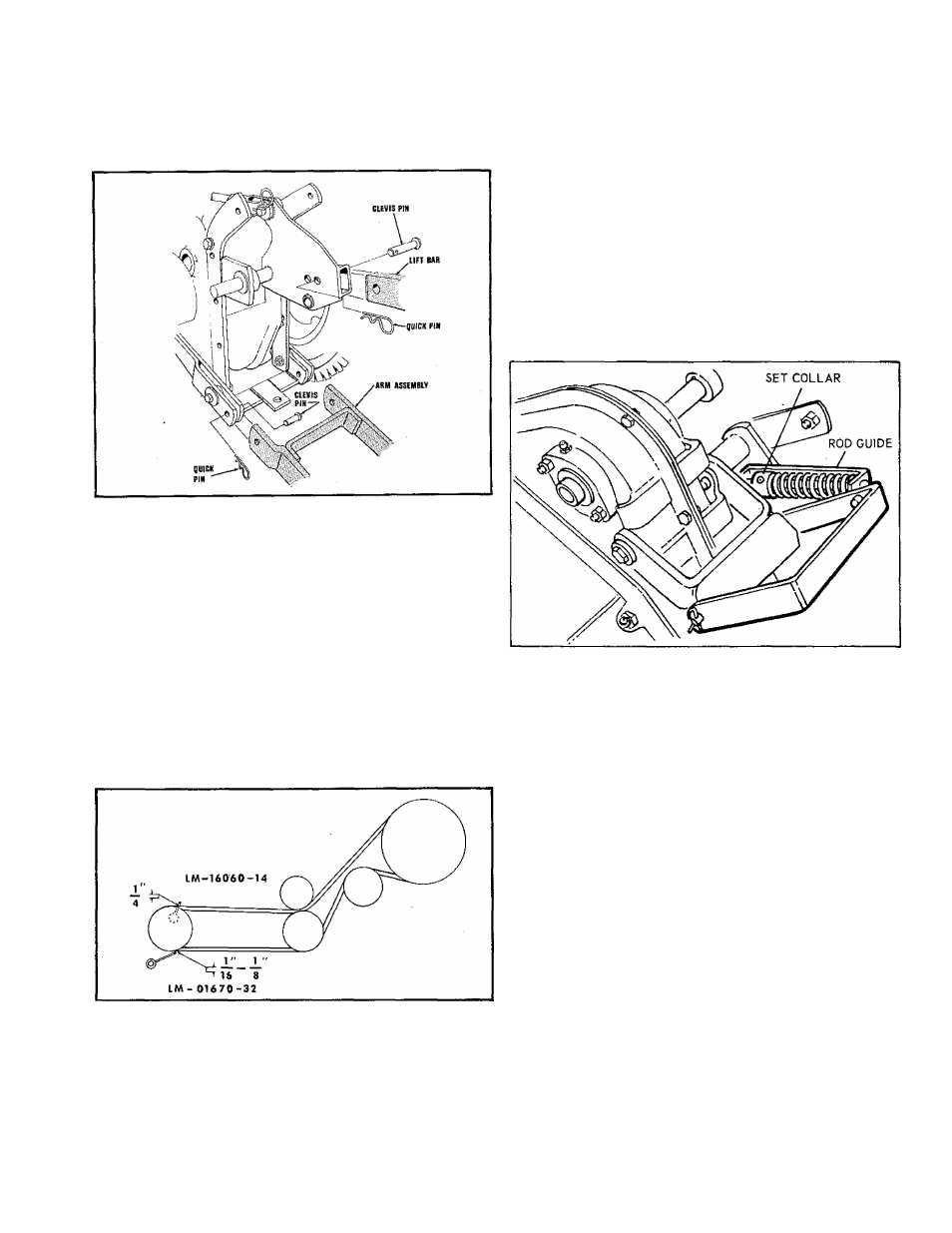
Position tiller at the rear of the tractor. Place the lift
lever in the fully back position. Put the tiller lift assem
bly into the tractor lift assembly and secure with clevis
pin and quick pin.
2.
Place tractor lift lever in forward position. Secure the
tiller frame assembly to tractor with the two clevis pins
and two quick pins supplied.
3. Slide idler arm assembly onto rear lift shaft.
4. Attach lower end of idler arm assembly to hitch member
with clevis pin and quick pin.
5. Assemble pulley to power take-off (PTO) shaft on bevel
gear housing. Using existing cap screw, washers, and
nut, secure belt stop to tractor.
6. Position belt
dh
pulleys and check that the belt is seated
properly in the pulleys, and that the pulleys are properly
aligned.
LUBRICATION
The belt that transmits power from the bevelgear box to the
tiller drive shaft is designed to provide long and satisfactory
service. Because of the special design of this belt, it is
urged that it is only replaced with genuine replacement
ordered from your dealer.
Adjustment of belt tension is controlled by the set collar on
the rodguide assembly. The tensionshould be correct when
there is about 1-1/4" clearance between the collar and the
bracket of the rod guide assembly with the tiller clutch lever
engaged. To increase the tension, release the tiller clutch
lever and loosen the setscrew in the collar. Slide the collar
up toward the spring and retighten the set screw. Check
the tension by engaging the tiller clutch lever. Avoid ex
cessive tension as it will cause premature belt failure.
There are grease fittings on each housing bearing and two
90° grease fittings are on the right hand side of the housing.
These fittings should be lubricated every three hours of
operation. Use a good grade of general purpose automotive
type grease applied with a standard grease gun. (Fittings
should be wiped clean before applying any grease.) Also
apply a few drops of lubricating oil to the moving linkages
of the tiller drive assembly occasionally.
Before starting the tractor engine, place the tiller clutch
lever in the disengaged position, and raise the tiller above
the surface of the ground. With the tractor engine running,
engage the tiller clutch and lower the tiller into contact
with the ground. As the tiller works into the soil, slowly
release the tractor clutch and move ahead. When coming
to the end of a row, raise the tiller free of the ground be
fore turning around.
Effective operation of the tiller will depend in a large degree
upon the operator. For example; when intending to till a
sod area into a seed bed for gardening, it obviously will re
quire several passes over the same path to break the sod
and ground into fine particles suitable for a seed bed. De
pending on the nature of the soil, it will be desirable to altar
the depth settings for the tiller on succeeding passes until
the desired depth is reached. When tilling in soil that has
been previously worked, it may be possible to till to the de
sired depth from the start.
The depth of tilling is regulated by the ground speed of the
tractor. The slower the ground speed the deeper the tilling
action.
NOTE: When using the rotary tiller on a tractor
equipped with the power lift attachment,
the power lift attachment must be in the
float position. Operating the tiller in the
hold position will cause the tiller tines to
propel the tractor at a dangerous speed .