Time guard circuits, Table 9 — physical data – Carrier 38AD028 Carri38AD044 User Manual
Page 9
Attention! The text in this document has been recognized automatically. To view the original document, you can use the "Original mode".
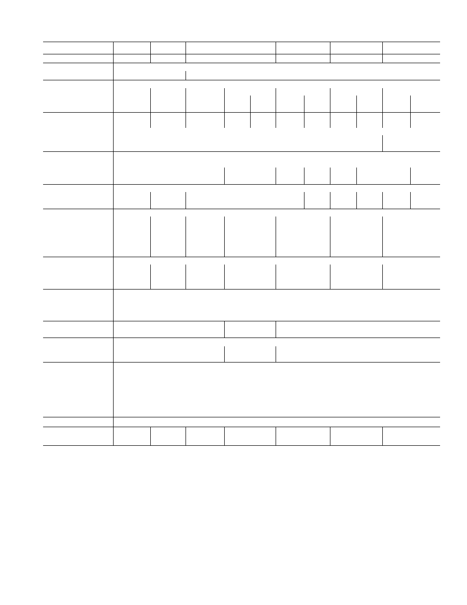
Table 9 — Physical Data
UNIT
38AD024
38AD028
38AD034
38AD044
38AB054
38AB064
38AB084
OPER WT (lb)
1750
1900
2300 '
3200
3145
3830
4960
REFRIGERANT
R-22
Oper Chg (lb)*
28 0
30 5
35 5
66 0
57 0
71
0
132 0
COMPRESSOR
Reciprocating Hermetic — 1750 rpm
Number
1
1
1
2
2
2
2
Model
0ÓED250
06EE266
06EE275
06EA
250
06ED
250
06EA
250
06EE
275
06EA
275
06EE
275
06EA
299
06EE
299
Cylinders
4
4
6
4
4
4
6
6
6
6
6
Oil (pt)
14
14
19
14
14
14
19
19
19
19
19
Crankcase Htr
1 25 Watts
Pro tection
Solid State &. Ckt Bkr
Thermotector & Ckt Bkr
Solid State
& Ckt Bkr
Cap. Control
Suction Pressure Cylinder Unioader(s
No. 1
Unloader Settings (ps g)
Load
76
78
78
88
-
79
~
79
-
79
Unload
58
60
60
66
-
66
-
66
-
66
No. 2
Unioader Settings (psig)
Load
76
76
-
76
-
76
_
76
Unload
-
58
58
-
58
-
58
-
58
COND FANS
Axic 1 Flow;
Direct Drive
Number
3
3
3
3
6
S
6
Rpm
1140
1140
1140
1 140
1140
1140
1 140
Diam (in.)
26
30
30
30
30
30
30
Motor Hp (ea)
1
1
Cfm
18,200
25,200
28,200
31,000
50,400
56,400
62,000
COND COIL
Plafe Fins; 3-rowt
Sections
1
1
1
2
2
2
Face (sq ft)
35 4
39 0
49 6
60 4
78 0
99 2
120 8
Capacity (lb)t
70
77
99
161
154
198
322
ELEC CONTROLS
Time Guard Circuit**
Pre^surestat
Du al
, Cutout
High ^ ^ .
Cut-in
375 Psig
275 Psig
, Cutout
Low ^ ^ .
Cut-in
29 Psig
29 Psig
29 Psig
44 Psig
45 Psig
63 Psig
Pressurestat
Capacity Control
Cutout
—
—
57 Psig
57 Psig
Cut-in
-
-
87 Psig
87 Psig
Pressurestat
Oi 1 Pressure Contro
1
Cutout
5 Psi Above Suction Pressure
Thermostat
Fan Cycling
No. 1
Opens, 70 F; Closes, 75 F
No. 2
Opens, 57 F; Closes, 62 F
Thermostat
Opens
Discharge Line
290 F; Closes, 210 F
PRESS. RELIEF
Fusibl
e Plug
DISCHARGE LINE
1
1
2
2
2
2
CHECK VALVE
■*Approximate charge for maximum system capacity Holding charge
factory supplied with all units
fUnit 38AD044 and 38AB084 have 4 row coil
^Storage capacity at 120 F condensing temp with condenser 80%
full of liquid
**Short-cycle protection
Time Guard Circuits
BASIC FUNCTIONS OF TIME GUARD CIRCUIT
on all units provide for normal (12 to 15 sec)
momentary delays after the thermostat closes and
before compressor(s) start. The circuit also pro
vides for a longer delay (4 min 45 sec to 5 min
30 sec) in the event of thermostat short cycling or
momentary power failure.
38AD024 THRU 044 UNITS
In addition to the basic functions, timers in
these units provide additional delays for oil
pressure switch bypass (40 sec), winter start
provision ( 1 5 0 sec) bypass of low-pressure switch
and part-winding start (1 sec), if used.
772