Start-up, J Page 7: L-ll, 3^- —-ii
Page 7: L-ll, 3^- —-ii
Attention! The text in this document has been recognized automatically. To view the original document, you can use the "Original mode".
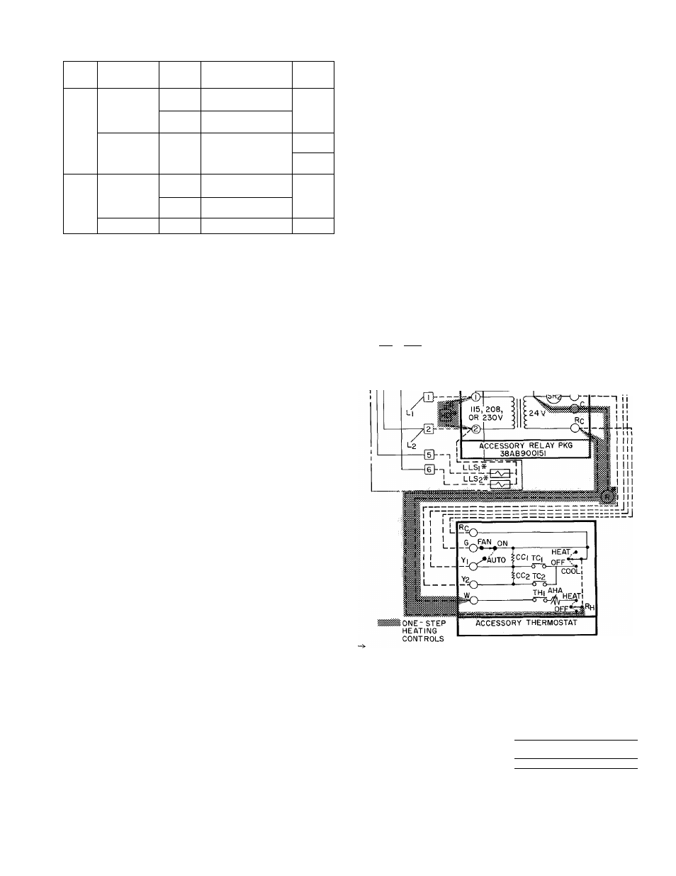
Table 7 — Maximum Field Wire Sizes
UNIT
SIZE
VOLTS
(60-Hzy
WIRE SIZE
CONN.
38AD
024,028,034
208
230
6 AWG to 350 MCM
TB
460
575
14 AWG to 2/0
044
460
575
208
230
6 AWG to 350 MOV!
TB
CT
38 A B
054,064
208
230
6 AWG to 350 MCM
CT
460
575
6 AWG to 3/0
084
All
6 AWG to 350 MCM-
CT
CT — Compression Terminal (attached to terminal block)
TB — Terminal Block (with integral compression terminal)
TB
&-
[1]--
[E--
0--
lEh
T
I
-I -
J TC2* ------------ E-------------------------------- --"fea-- TWO STEP COOLING 38AB054, 064 AND 084 , J LEGEND CR — Control Relay TC — Thermostat, Cooling LLS — Liquid Line Solenoid ---------Field Wiring TB — Terminal Board (at unit) *Field Supplied Fig. 10 — Control Circuit Wiring with Line Voltage (115, 208- or 230-volt) Thermostat LINE VOLTAGE REMOTE CONTROL - Install LOW-VOLTAGE REMOTE CONTROL - Install START-UP Preliminary Checks 1. Compressor oil level must be visible at sight glass in each compressor crankcase. Add oil if 2. Each compressor must float freely on its mounting springs. 3. All internal wiring connections must be tight, and all barriers and covers must be in place. Toggle switches for units 38AB054.,064 and 084 4. Electrical power source must agree with unit nameplate rating. 5. All service valves must be open. air stream under fan no. 1. 7. Crankcase heater must be firmly locked into the compressor crankcase. Leak Test the entire refrigerant system by the Pressure Method described in the Carrier Standard Service Techniques Manual, Chapter 1, Section 1-6. Evacuate and Dehydrate the entire refrigerant system by either of the methods described in the 38AB,054,064. 0^ SDRl CR)-------------------- •SDRir^ L-ll]------ l-2i (i^ —@ k 3^- —-ii THERMOSTAT HHOTATOTZ SUBBASE HH93AZ080 LEGEND AHA — Adjustable Heat SR — Solenoid Relay Anticipator TB -- Terminal Board cc — Cooling Compensator TC — Thermostat, Cooling CR — Control Relay TH — Thermostat, Heating HD — Heating Device — Factory Wired IFR IMS — Indoor Fan Relay -- ■ - Field Wired LLS — Liquid Line Solenoid n 1 Terminal Board Conn. R — Relay (Accessory) at Unit SDR — Solenoid Dropping Relay *Field Supplied Fig. 11 — Control Circuit Wiring with 24-Volt Accessories (38AB Units Only) 772
field-supplied line voltage thermostat(s) as shown
in Fig. 10 for two-step cooling. Wire liquid line
solenoid as shown.
field-supplied accessories as shown in Fig. 11 or
Fig. 12 for either two-step cooling or two-step
cooling, one-step heating. Wire liquid line solenoids
as shown.
necessary.
must be in “On” position.
6. Fan cycling thermostat sensing bulb must be in
Use R-22 at approximately 25 psig backed up with
an inert gas to a total pressure not to exceed 245
psig.
Carrier Standard Service Techniques Manual,
Chapter 1, Section 1-7.
— Indoor Motor Starter