Carrier 38AD028 Carri38AD044 User Manual
Page 6
Attention! The text in this document has been recognized automatically. To view the original document, you can use the "Original mode".
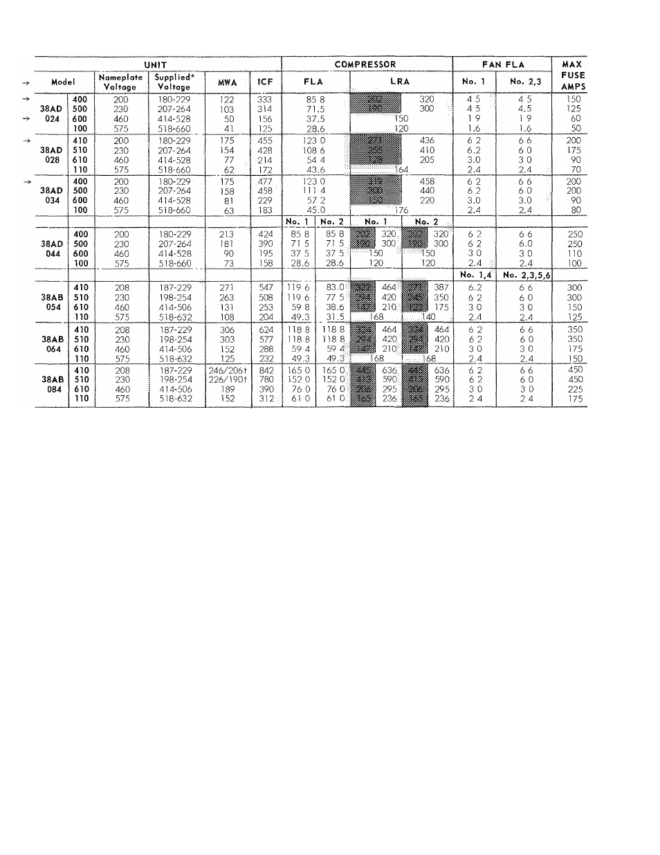
Table 6 — Electrical Data (3-Phase, 60-Hz)
f
Shaded
values
are
LRA
drawn
by
first
winding
of
part-winding
start
units
(not
standard
on
38AB054,064,
but may be field modified) See Note 1 Larger value is
total LRA.
FLA — Full Load Amps
ICF
—
Maximum
Instantaneous
Current
Flow
(sum
of
LRA
of
last compressor to start and FLA of all other motors in
unit, and control circuit current)
LRA
Locked Rotor Amps
MWA
—
Minimum
Wire
Amps
per
NEC,
Section
430-24
Values
based on maximum of 1% voltage drop in line.
*
*Units
are
suitable
for
use
on
electrical
systems
where
voltage
supplied to the unit terminals is never below or above the listed
limits
tUnits
38AB084
(208-,
230-volt
only) have
two power connections
Maximum wire size is 350 MCM each
NOTES
1
Dual compressor units have a 4- to 12-second delay between
first-
and
second-compressor
start-up
Units
are
supplied
with
either
across-the-line
or
part-winding
start,
depending
on
unit
size and voltage Refer to Electrical Data table Where two LRA
values are shown, units
are part-winding start, (all others are
across-the-line)
2
Units have factory-installed circuit breakers and/or pullout fuses
that
meet
NEC
requirements
for
branch
circuit
over-current
protection and in-sight disconnect Consult local codes
3
Maximum
Incremental
Current
Inrush
during
start-up
is
LRA
drawn by first winding of part-winding start unit (shaded area)
or
across-the-line
LRA
of
largest
compressor
when
part-winding
start is not available
4
Fans no 1 and 4 have single-phase speed control motors on 208-
and 230-volt units
5
Units 38AB054 and 064 which have two contactors, can be
converted
to
part-winding
start
by
addition
of
two
time-delay
relays (Carrier part no FIN67SK001 for 208- and 230-volt units,
or
no
HN67SK002
for
460-and
575-volt
units)
Two
additional
contactors are also required with 460- and 575-volt units to be
wired same as other part-wind compressors
On 38AD024 thru 034 units, power terminal
block is in the control box. Remove the outer
panel and remove the no. 10 screw on the door.
Swing open door, remove screws on barrier panel
and remove barrier panel. On 38AB054,064 and
084 units, remove two screws holding hinged sheet
metal barrier and swing open barrier.
Condenser fans must rotate clockwise when
viewed from above. If necessary, correct direction
of fan rotation by interchanging any two power
input wires at disconnect switch.
Affix crankcase heater decal to unit disconnect
switch.
Control Circuit Wiring —
Internal control voltage
on 38AD units is 115 volts.
Internal control
voltage on 208- and 230-volt 38AB units is the
same as unit voltage. On 460- and 575-volt 38AB
units, it is 115 volts. All control circuit wiring must
comply with applicable local and national codes.
Remote control wiring must enter unit control box
thru control opening (G on Fig. 1) and connect to
terminal block inside the control box.
772