Compressor mounting – Carrier 38AD028 Carri38AD044 User Manual
Page 3
Attention! The text in this document has been recognized automatically. To view the original document, you can use the "Original mode".
Compressor Mounting
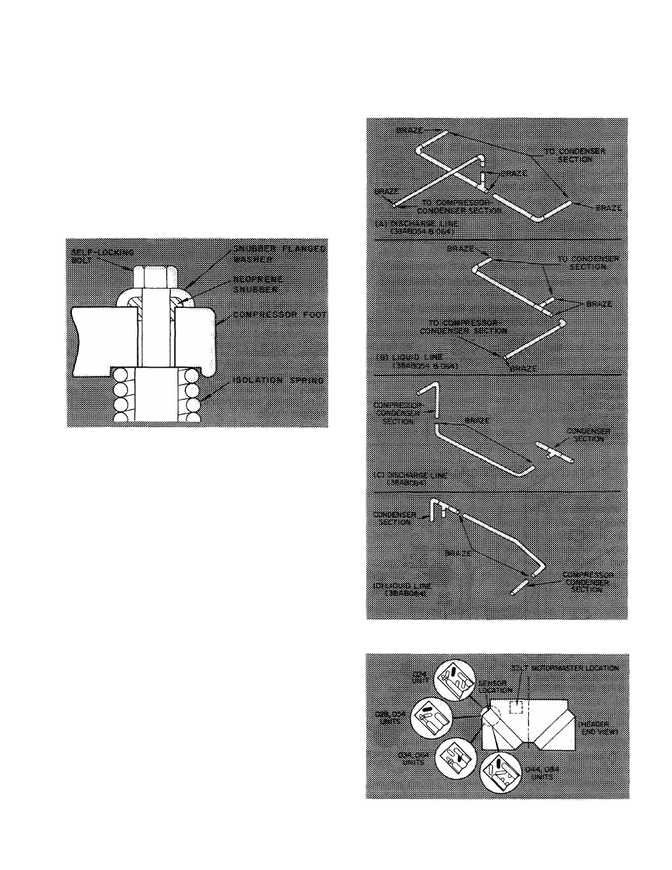
38AD024,028,034 UNITS - As shipped, com
pressor is held down by special self-locking bolts
and plain lockwashers. After unit is installed,
remove the self-locking bolts one at a time and
reassemble with flanged washers and neoprene
snubbers as shown in Fig. 4. Special flanged wash
ers and neoprene snubbers are shipped in a cloth
bag tied to one of the compressor feet. Tighten all
four bolts. Then, loosen each until the flanged
washer can be moved sidewise.
38AD044, 38AB054,064 AND 084 UNITS (com
pressors are mounted on a common support
channel) — Remove the four shipping bolts from
mounting channels prior to start-up.
Fig. 4 — Compressor Mounting
(38AD024,028 and 034)
Fan Thermostat
— Route the thermostat control
bulb and capillary (located in compressor section)
thru grommeted hole in compressor section base
pan. Do not kink capillary. Position bulb in inlet
air stream and secure to inlet air flange adjacent to
compressor section. Use clamp and screw provided
in parts package.
If accessory head pressure control damper
section is used, secure bulb to air inlet side of
damper. Use hole in damper frame.
Integrate Unit (38AB054,064 and 084 only) —
Connect refrigerant piping between the two sec
tions, using materials furnished with unit. Arrange
discharge and liquid lines as shown in Fig. 5 and
braze as indicated.
Electrically connect unit control box and junc
tion box on coil (only) section by using flexible
fan conduit furnished in the unit. Use the mating,
quick-connect, polarized plugs furnished in the two
sections to make the wire connections.
Motormaster® (32 Series) Head Pressure Controller
— Refer to MOTORMASTER Instructions shipped
with this accessory, plus the following information.
Control box and sensor location is shown in
Fig. 6.
Electrical connections are shown in Fig. 7.
Refer to unit label diagram as required. On 200-,
208- and 230-volt units, outdoor fan motor no. 1
(OFMj), located nearest the compressor, may be
used with MOTORMASTER without modification.
For 460- and 575-volt units, refer to Tabled for
field-supplied
components
needed
with
MOTORMASTER.
Fig. 5 — Refrigerant Connections
Fig. 6 - MOTORMASTER Control Box
and Sensor Location