Lubrication, Fig. 16 — fan adjustment – Carrier 38AD028 Carri38AD044 User Manual
Page 11
Attention! The text in this document has been recognized automatically. To view the original document, you can use the "Original mode".
allow unit to start under low-ambient conditions.
An evaporator freezestat must also be installed in
series with the control thermostat(s) to prevent
coil freeze-up (See lower part of Fig 15 — EDT
Wiring section.)
LIQUID LINE PRESSURESTAT - Connect to
system liquid line service valve port. Connect
switch into control circuit as shown on unit label
diagram or in Fig. 15. Pressurestat is set to cutout
at 5 psig with a differential of 10 psig. Do not
change setting
DEFROST THERMOSTAT - Position switch so
that moisture cannot enter switch insulator. Install
control with approximately 2 in. of top of thermo
stat capillary passing thru lower part of evaporator
cod and with remainder of capillary inserted
between fins on entering air side of coil. Connect
thermostat electrical contacts into indoor cooling
thermostat circuit or in series with compressor
holding coil.
Thermostat is set to cut out at 25 F and cut in
at 55 F. Contact rating is 16 amps and 230 volts.
As evaporator coil frosts, cod fin temperature
drops to thermostat cutout setting, and stops
compressor. Evaporator fans keep running to
defrost cod with room air. As indoor coil defrosts,
fin temperature will rise to thermostat cut-in
setting. Compressor starts when cooling is required.
NOTE. Use a defrost thermostat on all systems
operating with outdoor temperatures below 45 F.
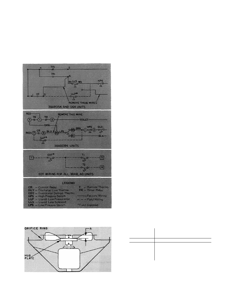
Fan Adjustment
— When replacing a fan, adjust fan
until top surface of hub plate is below the top of
the orifice ring as indicated in Fig. 16. Then,
tighten both setscrews, located over the keyway of
the fan hub of the motor shaft. Seal recessed area
of fan hub bore with Permagum to prevent rusting.
Lubrication
FAN MOTORS have permanently lubricated bear
ings. No provisions for lubrication are made.
COMPRESSOR has its own od supply. Loss of oil
due to a leak in the system should be the only
reason for adding oil after the system has been in
operation.
To Add or Remove Compressor Od
1
.
2
.
3.
4.
Fig. 15 — Unit Wiring Changes for
Winter Start Control
Stop compressor and close suction service valve.
Pump down compressor to 2 psig. Stop com
pressor and close discharge shutoff valve.
Relieve crankcase pressure by disconnecting
line, at compressor, which goes to low-pressure
connection of od safety switch.
Add oil thru oil filter connection.
Remove od thru drain plug in bottom cover.
Remove small amounts of od thru od discharge
connection with compressor running.
roft
3»^ A ...............................
i Fan
............L " '
38AD034
3SAD044
38
a
S«54
38A8iSii4
Fig. 16 — Fan Adjustment
11