General operating sequences, Operating sequence-heating, Operating sequence — cooling – Carrier 48DM User Manual
Page 2
Attention! The text in this document has been recognized automatically. To view the original document, you can use the "Original mode".
C
a
BXIO??-. D
o
iiot »so màfcii»s to'
piìot oa ioimriiiient pOotumit^aS' fó'pos&ifcìe
elect ncsJ sitot.^ ha/:,arii.
GENERAL OPERATING SEQUENCES
These sequences apply to both natural and LP
gas units in normal operation after initial start-up
Operating Sequence-Heating
NATURAL GAS AND LP UNITS WITH INTER
MITTENT PILOT
1 Thermostat selector switch at HEAT or AUTO.
Thermostat dial set above room temperature,
2. Pilot gas valve opens Gas flows to pilot and
ignites Pilot flame setting probe causes main
gas valve to open Gas flows to main burner and
ignites.
3. TDR starts indoor fan motor in 30 — 45
seconds
4 When thermostat is satisfied both pilot gas and
main gas valves close. Pilot and main burner
flames arc extinguished.
5
TDR stops indoor fan motor in 1- to 1-1/2
minutes.
6
Pilot is on only when thermostat calls for
heating
Operating Sequence — Cooling
1
Unit energized. Thermostat selector switch at
COOL or AUTO Thermostat dial set below
room temperature
2 Indoor and outdoor fans and compressor start
3. When thermostat setting is satisfied, fans and
compressor stop.
Automatic Operation
— Power and gas on. Room
thermostat (control center) set at AUTO. Fan
switch (on control center) set at AUTO.
Unit performs as described in the operating
sequences above on call for heating or cooling.
Automatic changeover type thermostat is required
Continuous Fan Operation
— With power supplied
to unit and fan switch at ON position, indoor fan
remains on at all times.
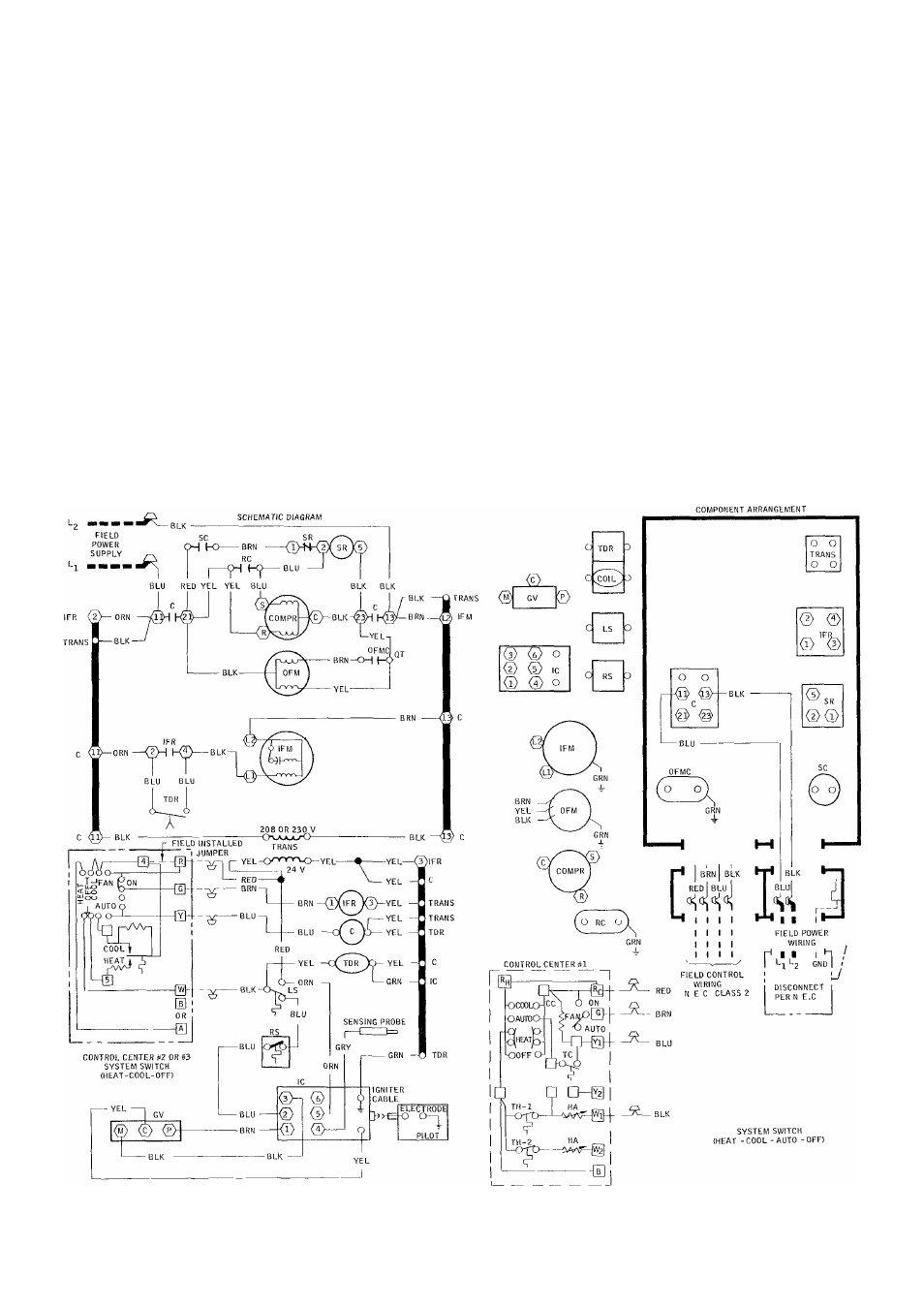
Fig. 1 — Label Diagram, 48DL,DM006; 230-1-60
2