S&s ‘d’ c, Read tuning instructions, Arburetors – Zipper's Performance G/D Carbs User Manual
Page 4
F
oR
s&s ‘d’
c
aRbuRetoRs
GENERAL INSTRUCTIONS
ThunderTech Products - 6655-A Amberton Drive - Elkridge, MD - 21075 - PH: (410)579-2929 - Fax: (410)579-2835
A.
Tapping bowl vent for fitting
EXTERNAL FLOAT BOWL VENT
ADJUSTABLE AIR BLEED
CIRCUIT
If you do not have the facilities to properly
install this fuel module, professional
installation is available from Zipper’s.
High volume shops may want to invest in
our ThunderJet installation fixture (shown
in the photos p/n 713-910) which securely
holds the carb body and float bowl at the
correct positions for machining. Use with a
mill when installing ThunderJets in all S&S
model E/G/B/D carbs. Read all instructions
fully and carefully before proceeding any
further.
Loosen drain plug and remove float bowl
and manifold. Install two (2) studs in carb
manifold bosses; use these to center
carb in milling machine vise. Be careful
not to over tighten carb in vise. The first
two steps are recommended to further
enhance your carb’s performance along
with the installation of your ThunderJet.
1. Pressure in the float bowl is stabilized
with the addition of this external bowl vent.
Locate the new vent hole in the rear of the
carb wall .438” above bowl gasket surface
and 1.906” from the manifold flange of the
carb. Open hole with a small center drill
then plunge a 5/16” end mill to a depth of
.562” below the raised surface. Use a ½”
countersink to chamfer the raised surface
to help start the tapping process. Chamfer
only slightly not touching the lower level
surface. Tap with 1/8” NPT tap. Install
1/8” NPT street elbow and 1/8” NPT x 3/8”
hose nipple using a suitable thread sealer.
The hose nipple should be positioned
pointing up.
Air bleed passage drilled & tapped
for jet.
Fuel tube hole drilled/tapped, area
relieved for ThunderJet
THUNDERJET INSTALLATION
2. Earlier versions of “D” carbs are
manufactured with a fixed size air bleed
passage (current “D” models are now
machined for adjustable air bleed jets).
This modification will allow the tuner to
adjust the main jet air bleed size for more
control over the main jet circuit signal
NOTE: On “D” applications using only (1)
ThunderJet, the ThunderJet mounts on the
side of the carb facing the rear of the bike
(9:00 position). If using (2) ThunderJets fol-
low all instructions below and mount one
each in the 9:00 and 3:00 positions.
timing and fuel volume. Locate the fixed
air bleed hole and bore with ¼” drill until
you reach the cross drill in carb (DO NOT
GO PAST CROSS DRILL!!). Spot face the
area with 1/2” end mill for mating surface
of jet. Use 5/16-24 starter tap in hole and
remove to use a 5/16” bottom tap to finish
job. Original air bleed size is .042” and the
suggested range is .054-.072”. Use S&S
main jets for this.
9:00 POSITION
3. Drill and tap hole .750” from the end
of the carb throat, offset slightly above the
throttle butterfly shaft. Use a letter ‘i’ (.272”)
drill and tap 5/16”-24 thread. You will be
drilling through the middle of the original
float bowl vent passage; this is OK, it will not
affect performance or operation of the carb.
4. You then need to relieve the area
around the hole you just threaded for
air bleed spacer clearance. This is best
accomplished on a vertical mill with a 3/4”
end mill. With the cutter starting near the
bowl area, mill toward the top of the carb,
removing material at least ¼” above the
centerline of the fuel tube hole. Use care
not to break into the enrichener air passage
located above the hole. Leave .170-.185” of
carb wall for the short threaded portion of
the fuel delivery tube.
Double-nut and tighten fuel tube
in place
D
o
noT
oveRTighTen
boDy
oR
fuel
Tube
bReakage
will
ResulT
!
ThunderJet body (nipple down),
bowl cent & air bleed jet in place.
5.Install the fuel delivery tube from the
inside of the carburetor throat out. Double
nut the delivery tube using (2) ¼”-28 jam
nuts and carefully lock into carb throat
(DO NOT OVERTIGHTEN). Remove jam
nuts (not needed after this step).
6. Install air correction spacer, o-ring, and
ThunderJet with fuel nipple facing down
towards float bowl. Trim small opening
side of air correction spacer, if needed,
to achieve a hand tight location 1/6 of a
turn from permanent location and finish
tightening with wrench. (.006” trim = 1/6
turn).
3:00 POSITION
(Part 2 of twin T-Jet installation)
7. Drill and tap hole .950” from the end
of the carb throat, offset slightly above the
throttle butterfly shaft (letter ‘i’ (.272”) drill
and 5/16”-24 tap).
8. You then need to relieve the area around
the hole you just threaded for air bleed spacer
clearance. This is best accomplished on a
vertical mill with a 3/4” end mill, on center
of your threaded hole. Be certain to leave
.170-.185” of carb wall for the short threaded
portion of the fuel delivery tube. (Some D
carbs are equipped with dual float bowl vent
passages (forward and rear of carb throat);
you will be cutting through the forward vent
passage if equipped. This passage must
then be plugged, as its location will subject
the passage to positive air pressure at
speed, resulting in fluctuating pressure in
the float bowl, adversely affecting jetting.
Drill the passage past the ThunderJet
mounting area and tap it 5/16”, 3/8” deep
and plug it with a set screw. The external
vent described in step 1 must be performed
to replace this original vent.)
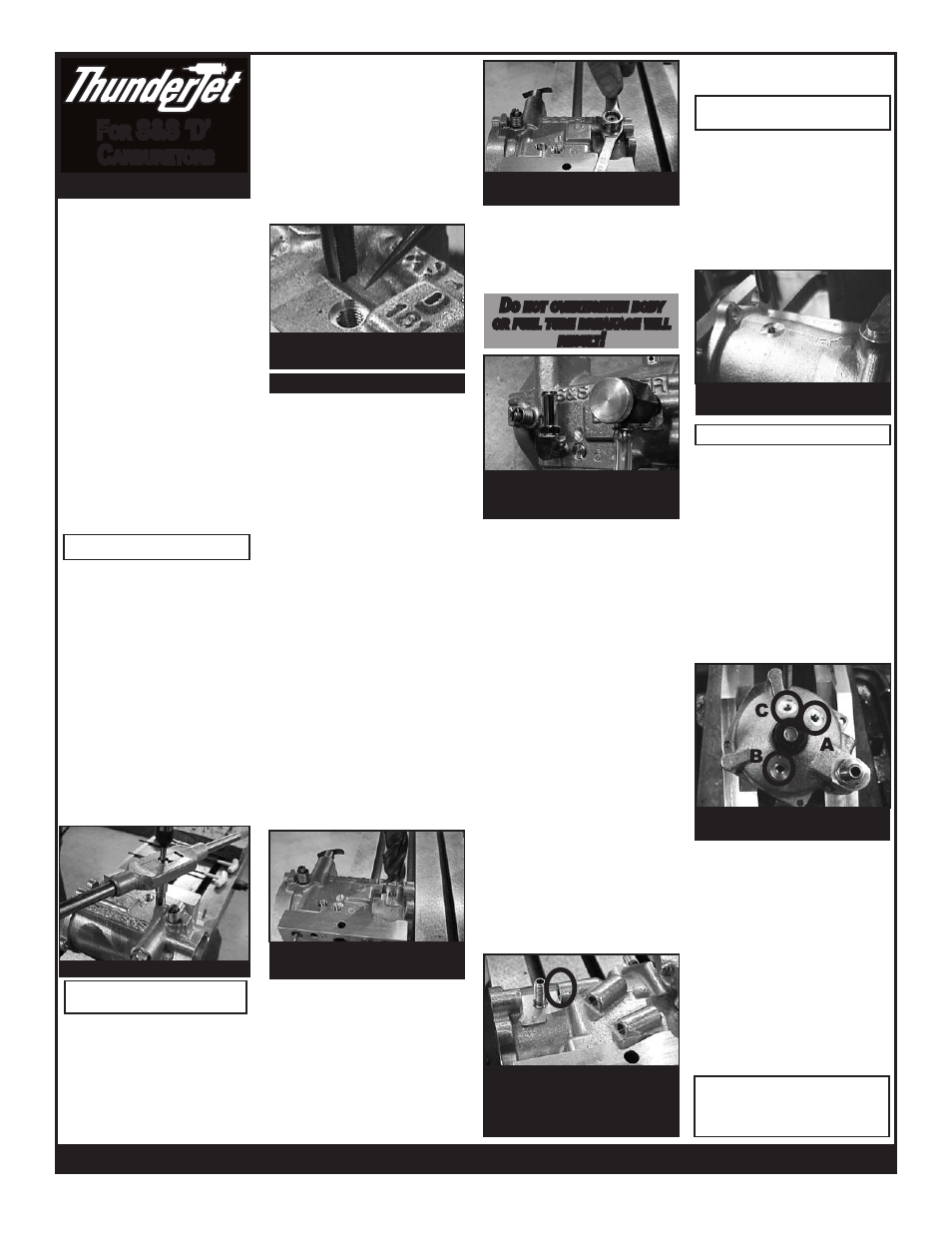
Hole A (9:00 position), B (3:00),
C (12:00)
13. ReaD Tuning
insTRuCTions
FOAT BOWL
PRO-STOCK OPTION
(12 O’Clock Position)
Spot faced, drilled/tapped for 3rd
T-Jet (Pro-Stock option)
fuel tube hole drilled/tapped,
area relieved for T-Jet, fuel tube
installed. Circle shows where vent
passage should be plugged
9. Follow steps 5, 6 & 7 from the 9:00
segment.
If a third ThunderJet is desired, drill, tap
(letter ‘i’ (.272”) drill and 5/16”-24 tap) and
spot face TOP center of carb 1.200” from air
cleaner backing plate surface, leaving .170-
.185” wall thickness for the short threaded
portion of the fuel delivery tube. Follow
steps 5, 6 & 7 from the 9:00 segment. Point
hose nipple towards rear of the bike and
slightly inward.
10. Clamp bowl to mill table at 35 degree
angle. See photo for bowl nipple location(s).
At the bottom of float bowl, beside drain,
drill a #3 hole and tap ¼”-28. Spot face the
area around the hole to give a flat surface
for the o-ring to seal against and reduce
thickness enough to allow the nut to attach
on the inside of the bowl. Install fuel nipple
and o-ring then secure inside bowl with nut
provided (no washer). Stake threads with a
punch to lock nut in place (make sure this
device does not interfere with float action or
movement). Repeat for multiple bowl nipple
locations.
12. Clean all carb parts; reassemble
and install fuel line with clamps provided
(trim fuel line if needed). Install on engine.
Install fuel line, turn fuel valve on and check
for leaks before starting engine!!