S&s ‘g’ c, Read tuning instructions – Zipper's Performance G/D Carbs User Manual
Page 3
ThunderTech Products - 6655-A Amberton Drive - Elkridge, MD - 21075 - PH: (410)579-2929 - Fax: (410)579-2835
F
oR
s&s ‘g’
c
aRbuRetoRs
GENERAL INSTRUCTIONS
F
oR
s&s ‘g’
c
aRbuRetoRs
READ INSTRUCTIONS FIRST!
Please read all instructions
fully and carefully before
proceeding.
Drilled, tapped and spot faced for
fuel delivery tube.
Body and the air correction spacer
installed, nipple facing front of
bike.
Drilled, tapped, spot faced for
adjustable air bleed jet.
External bowl vent machined in
body.
If you do not have facilities available
to properly install this module,
professional installation is available
from Zipper’s. High volume shops
may want to invest in our ThunderJet
installation fixture (shown in the
photos, p/n 713-910).
This securely holds the Carb body
and float bowl at the correct positions
for machining. For use with a mill
when installing ThunderJets in all
S&S model E/G/B/D carbs.
1. Loosen the drain nut and remove
your float bowl from the Carb.
Remove emulsion tube with main
jet from Carb body and remove the
accelerator pump rod, rubber bellows
and discharge o-ring. Looking into
Carb throat, turn Carb counter-
clockwise at approximately an 11
degree angle and clamp in vice.
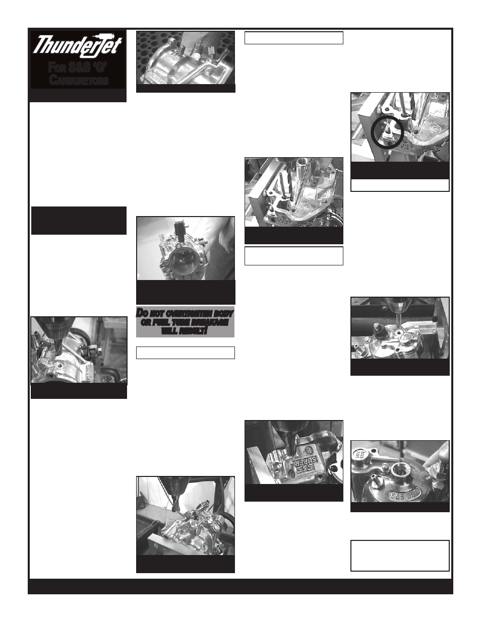
2. The location for drilling, tapping
and spot facing the fuel tube hole is
.950” from the air cleaner mounting
surface; use the upper left corner of
the “T” in the word “SHORTY” for
locating the other axis. Drill a letter “I”
hole, tap 5/16-24. Using 1/2” end mill,
counterbore hole until you maintain a
3/16” (.187) wall thickness (photo 1).
4. Locate air bleed passage plug
above S&S nameplate on throttle
spool side of Carb. Clamp Carb body
at approximately a 45 degree angle.
Center a 5/16” end mill over the plug
and spot face lightly to flatten and
align. Use a center drill to start and
then drill the plug with a #19 drill bit and
tap 5mm x .8mm for air bleed (photo
4). Install air bleed jet (same type jet
used in ThunderJet). Jet sizes range
from 130-170 for most applications
(see chart).
3. Remove jam nuts (no longer
needed). Install the air correction
spacer (small opening out), o-ring and
ThunderJet body on to Carb. Fuel line
nipple should point to front of bike and
slightly toward the air filter for hose
routing (photo 3). Trim small opening
side of air correction spacer, if needed,
to achieve a hand tight location 1/6 of a
turn from permanent location and finish
tightening with wrench. (.006” trim =
1/6 turn). DO NOT OVERTIGHTEN
BODY OR FUEL TUBE BREAKAGE
WILL RESULT!!
5. Clamp Carb in vise upside down.
Locate original internal air bleed hole
(photo 5) to be blocked off. (’04 and
earlier) Carefully drill this passage with
a #21 (.159”) drill bit until you break
into cross passage in Carb body. Tap
hole with a 10-32 tap, blow passage
out with compressed air, then plug with
supplied 10-32 slotted screw. (’05 and
later) These carbs come with a main
jet style air bleed jet; remove the jet
and plug the hole with the supplied
5/16-24 set screw.
Adjustable Air Bleed
Original air bleed passage tapped
for block-off screw.
Fuel delivery tube installed.
Original Air Bleed Blocking
6. We have found additional
performance and increased fuel
pressure stability in the float bowl by
relocating and modifying the float
bowl vent passage. Clamp body
upside down at a 45 degree angle.
Remove the existing 5/16” bowl vent
plug (photo 6). Using a small center
drill or wiggler, locate the center of the
hole where plug was removed. Mark
a spot 7/16” from the casting surface
where vent plug was removed, toward
top of Carb. Using a small center
drill, break through to existing vent
passage. Finish hole using a 5/16”
2-flute end mill at this angle. Cut only
deep enough to enter existing vent
cross drill!
In extreme high velocity applications,
we recommend plugging the original
vent passage at the air cleaner backing
plate surface (tap opening 5/16-24).
Use the 5/16”-24 plug removed from
the vent passage to plug the original
opening, as extreme airflow can create
a vacuum that may draw fuel through
(Optional) Bowl Vent
Relocation
3. Install the fuel delivery tube
from the inside of the Carb throat
out (photo 2). Using (2) ¼”-28 jam
nuts, double-nut the fuel delivery
tube outside of the Carb throat and
carefully lock tube into Carb throat
until all or most of the air bleed
segment is exposed.
D
o
noT
oveRTighTen
boDy
oR
fuel
Tube
bReakage
will
ResulT
!
Remove bowl vent passage
plug.
Bowl drilled, tapped and spot
faced for bowl fitting
Bowl fitting installed
7. Remove float from bowl. Set bowl
at a 20 degree angle on sine plate.
Drill a #3 hole between bowl drain plug
and accelerator pump housing and tap
with ¼”-28 tap. Spot face hole center
(kiss) just enough to give a flat surface
for o-ring to seal against (photo 8).
Install fuel nipple and o-ring, secure
inside bowl with lock washer and nut
provided (photo 9). Make sure this
device does not interfere with float
action.
8. Thoroughly clean Carb, check low
speed and main jet sizes for engine
compatibility (see tuning tips), re-
assemble Carb and install fuel line with
clamps provided. Fuel hose is routed
to front of bike. See tuning instruction
page for jetting instructions.
Float Bowl
9. ReaD Tuning
insTRuCTions
the vent and uncontrollably richen
the mixture. Install the plug just deep
enough to be slightly below the air filter
mounting surface, and use Loctite. If
you choose not to do this modification,
at least remove the vent plug and
discard it.