Winco ECV2512-3 User Manual
Page 8
Page 6
60706-130
7150-01
continuity (any reading -should be infinite resistance). The
field is grounded and should be repaired or replaced. To
determine which of the fields is grounded, cut the connec
tor between the two coils and retest to determine which
coil has the low resistance path.
4.
Disconnect field leads (F1 & F2) from regulator.
5.
Set multimeter to read resistance, and connect the meter
leads to the field leads. If field is open, meter will read
infinite resistance (very high ohms). Repair or replace
field if it is open. Typical resistance for these fields vary
from 11.2 to 12.1 ohms.
6.
Leaving one meter lead connected to the field, connect the
other meter lead to the field shell. If meter indicates
continuity (any reading -should be infinite resistance) the
field is grounded and should be repaired or replaced. To
determine which of the fields is grounded, cut the connec
tor between the two coils and retest to determine which
coil has the low resistance path.
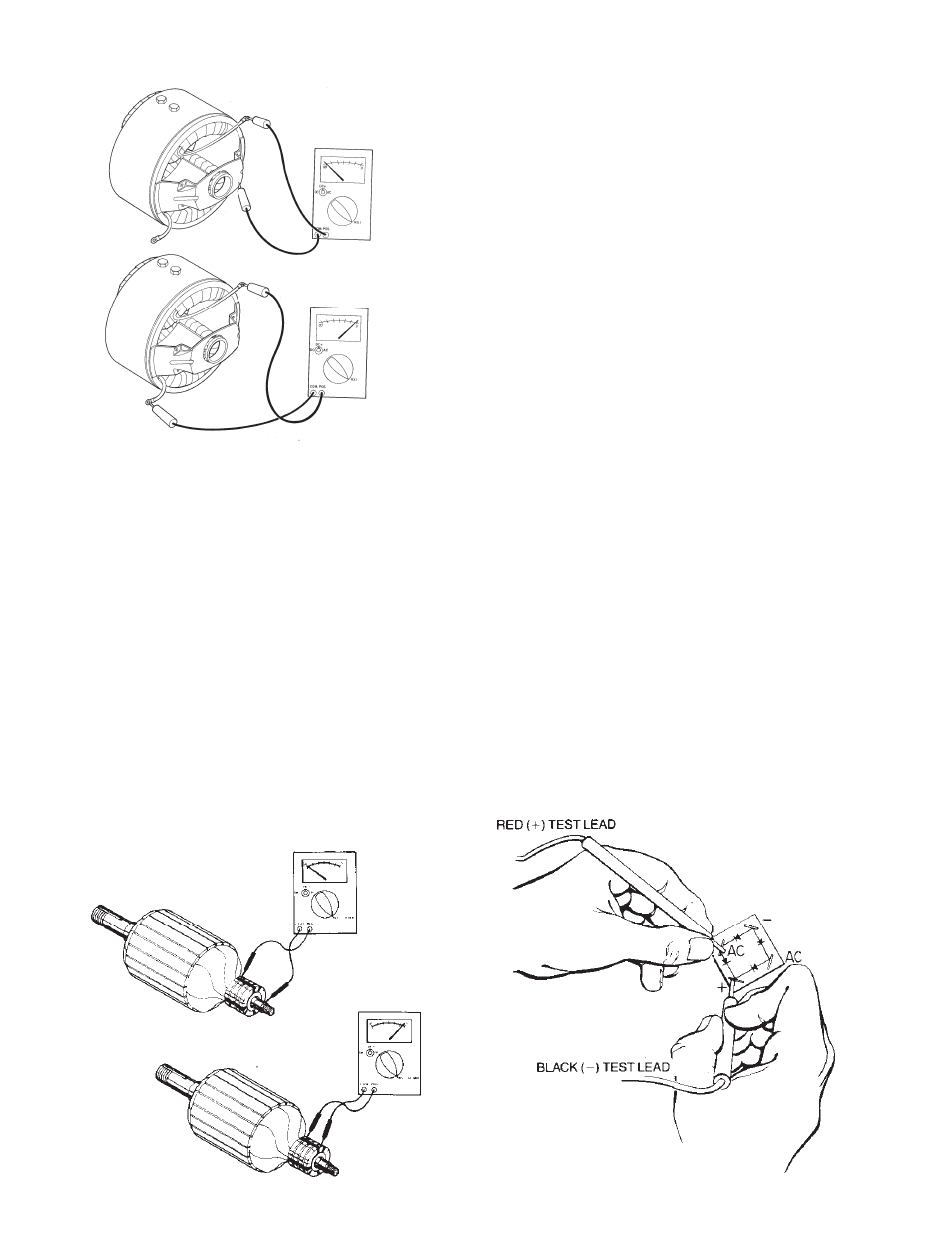
Testing the Armature for Opens and Grounds
1.
Remove all brushes.
2.
Ground fault test - set multimeter to read high resistance
(meg-ohms).Holding one meter lead against a clean spot
on the armature shaft, touch the other lead to each of the
slip rings (one at a time) while observing the meter. If
meter indicates continuity (any reading lower than one
meg- ohm), the armature is grounded. Dirt between the
slip rings and on the insulator surface can cause ground-
ing. If grounding was indicated, carefully clean all dirt off
the slip rings and their insulators and then recheck it.
Replace the armature if it is grounded and unrepairable.
3.
Open Test. Set meter to read low resistance (R x 1
ohms). Holding one meter lead on surface of slip ring
No. 1, touch other meter lead to surface of slip ring No.
2 while observing the meter. Meter should indicate
continuity (low resistance - less than one ohm is
typical). If the meter indicates open circuit (infinite
resistance) part of armature winding is open. This may
be caused by a repairable defect in the connection at
the slip ring, however generally an open armature will
have to be replaced. Continue reading the continuity
between slip ring No. 2 to No. 3 and No.2 and No.4. All
the slip rings should have continuity to slip ring number
2, the neutral ring.
Testing Rectifiers
The field excitation is supplied through a full wave bridge
rectifier. This type of rectifier has four terminals, two AC, a
DC positive and a DC negative.
A rectifier may be tested in the following manner:
1.
Disconnect all leads from rectifier.
2.
Connect the red ohmmeter lead to the positive DC (+)
terminal.
3.
Connect the black lead to each of the AC terminals in turn.
Either a high or low resistance reading will be obtained.