Installation – Winco 75FPTOC-17 User Manual
Page 5
Page 3
60706-125
7315-000
E. All four generator mounting pads must rest firmly on the
foundation. Install shims if necessary to even out the founda-
tion under the mounting pads then bolt the generator firmly in
place.
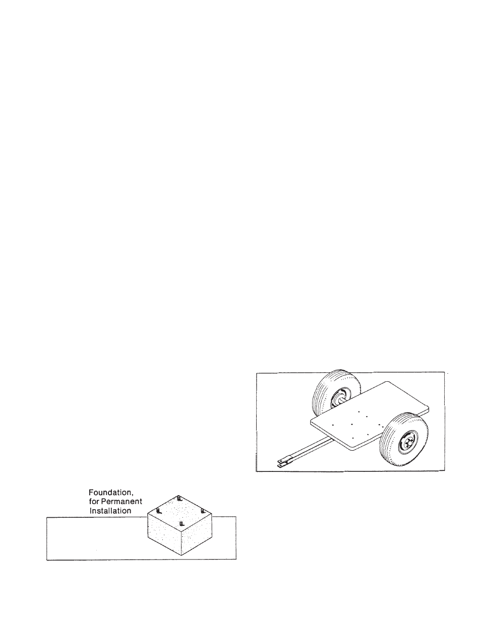
TRAILER MOUNTING
Mount the generator on a trailer if you plan to use it as a
portable power source. See Figure 4. When selecting or
building a trailer to mount the generator, consider the follow-
ing points:
A. The trailer construction must be strong enough to support
the generator.
B. The design of the trailer must enable the trailer to remain
stable during operation, and to resist tipping caused by
generator starting and reflected load torque.
WARNING: Personal Injury & Equipment Damage
TRAILER MAY TIP OVER AND CAUSE INJURIES IF
WHEELS ARE NOT SPACED FAR ENOUGH APART.
C. The trailer height and mounting position of the generator on
the trailer should enable aligning the drive shaft (tumbling bar)
in a straight or nearly straight line between the power take-off
and generator input shafts. Misalignment must be less than
15 degrees during generator operation, even though the
mechanical design of the tumbling bar would allow greater
misalignment.
D. The generator mounting area of the trailer bed should be
flat.
All four generator mounting pads must rest firmly on the trailer
bed. Install shims if necessary to even out the bed under the
mounting pads, then bolt the generator firmly in place.
DANGER: Equipment Damage
If cable-to-pin connections are loose, arcing and heat damage
to equipment can result.
5. Insert the brass pin (with cable) into the plug body, and line
up the retainer pin holes in the brass pin with those in the plug
body.
6. Insert the retainer pin, and tap it firmly into place. The
retainer pin will protrude approximately 3/8" when fully seated.
(See Figure 1.)
7. Repeat steps 4 through 6 for each brass pin. Make sure to
connect the neutral lead (cable), identified and color coded in
conformance with the applicable local electrical codes, to the
large diameter pin (“N”) on the plug.
WARNING: Electrical Shock
DURING THE NEXT STEP, THE LOAD DISCONNECT PLUG
SHOULD NOT BE PLUGGED INTO ITS RECEPTACLE. ALSO,
MAKE SURE THAT THE EQUIPMENT TO WHICH THE PLUG
LEADS (CABLES) ARE BEING CONNECTED IS NOT ENER-
GIZED (LIVE).
8. Strip the insulation off the free end of each of the plug leads
(cables), and connect them to the load transfer switch (or
directly to the load).
Installation
FOUNDATION MOUNTING
Mount the generator on a foundation if it is to be used as a
permanent or standby power source (see Figure 2). See
“TRAILER MOUNTING” if generator will be used as a portable
power source (see Figure 3). When planning a foundation
consider the following points:
A. The foundation location should enable aligning the drive
shaft (tumbling bar) in a straight or nearly straight line be-
tween the power take-off and the generator input shaft.
Misalignment must be less than 15 degrees during generator
operation, even though the mechanical design of the tumbling
bar would allow greater misalignment.
B. The foundation must be solid enough to absorb generator
starting and reflected load torque during operation.
C. The foundation surface should be flat.
D. Space is required around the generator for mounting
switching devices, making connections, and for servicing.
Figure 2
Figure 3
Trailer, for Portable Operation